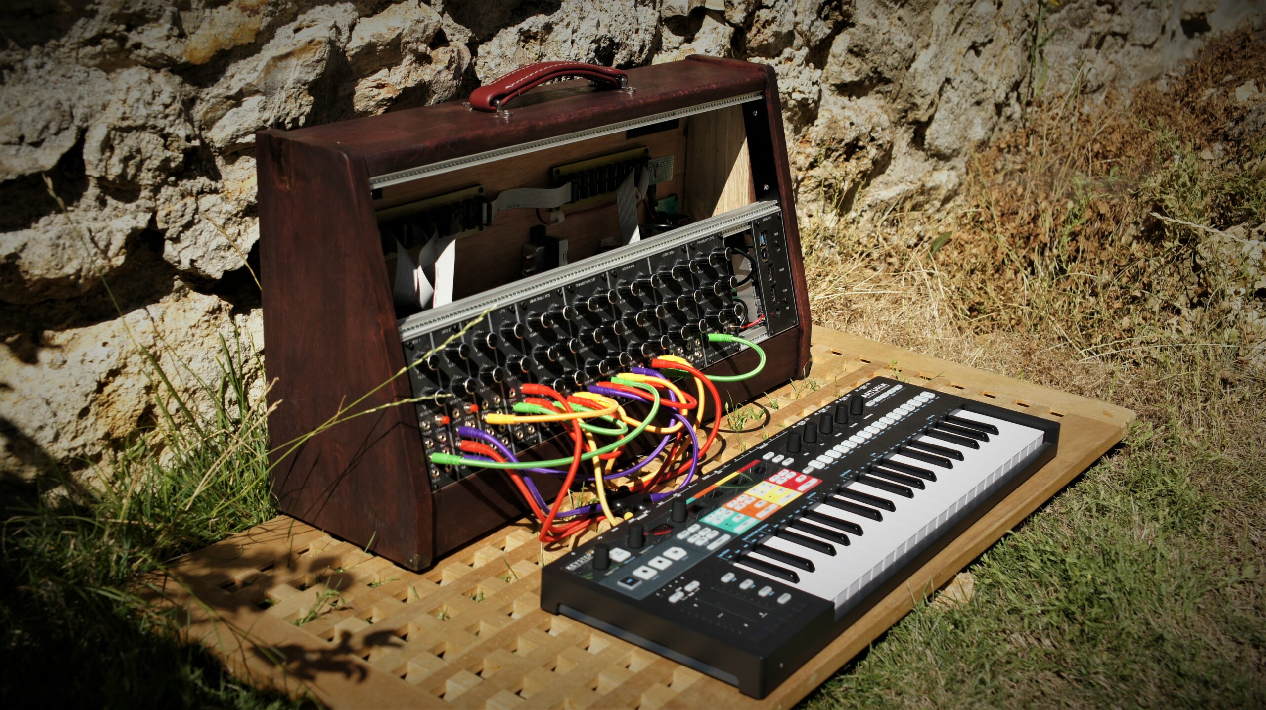
After two years of work, with some CNC and 3D printing machines described here, I have released a first prototype of my DIY polyphonic modular synthesizers, called “Heritage Modular”.
The project is hosted here: Heritage Synthesizers
After two years of work, with some CNC and 3D printing machines described here, I have released a first prototype of my DIY polyphonic modular synthesizers, called “Heritage Modular”.
The project is hosted here: Heritage Synthesizers
Currently, the last Launchpad-X is not yet supported by FL-Studio 20.
I have developed a small Java application able to make it compatible with FL-Studio by converting Lauchpad-MK2 messages to Lauchpad-X format.
Tested only under Win10, but should work on other Windows versions, or MacOS.
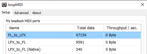
You need to install a Virtual MIDI loopback software such as https://www.tobias-erichsen.de/software/loopmidi.html
Then, setup three Virtual MIDI ports as below:
[Launchpad-X] <=== [Java] <=== FL_to_LPX <=== [FL-Studio]
[Launchpad-X] ===> [Java] ===> LPX_to_FL ===> [FL-Studio]
[Launchpad-X] ===> [Java] ===> LPX_to_FL (Native) ===> [FL-Studio]
Connect your Launchpad-X.
Then you need to install and run the Java application: https://github.com/f1oat/Launchpad-X-gateway
Configure it as below:
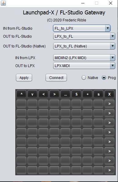
If you have used the exact recommended names for loopMidi configuration, the Java application should select automatically the right ports. Otherwise, you will need to do it by hand by using the drop down menus, and click “Apply”.
Before launching FL-Studio, you can now click on “Connect” button. As a result, all pads should now become dark. If not, that means you have a configuration problem.
Then, launch FL-Studio. You have to make the connection to the loopMidi virtual ports and declare a “Launchpad MK2” device as below:
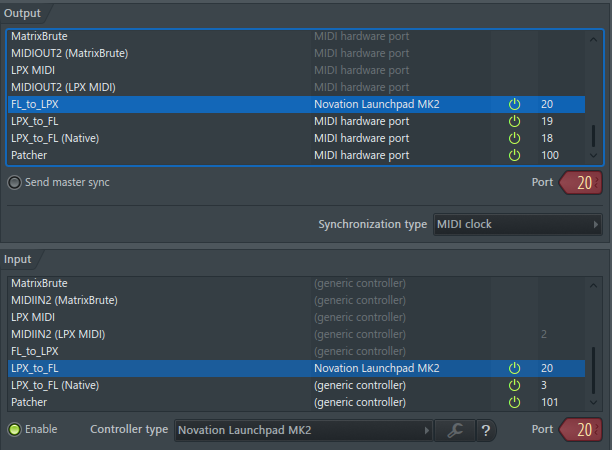
Note:
When everything is configured, you can load a performance mode song.
You should see pads getting several colors according to the Playlist.
Also, you should see the same colors on the Java application:
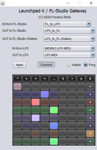
You can now play with your Launchpad-X. The behavior will be the same as for MK2. See description here: https://forum.image-line.com/viewtopic.php?t=147179
The “Native” radio button can be used to make the Lauchpad-X going back to power-on status, and send MIDI messages in “Note mode” or “Custom mode”. MIDI messages will be received by FL-Studio on port 3 for our configuration example. When you are in native mode, you can no longer use the performance mode.
Enjoy!
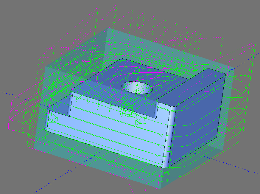
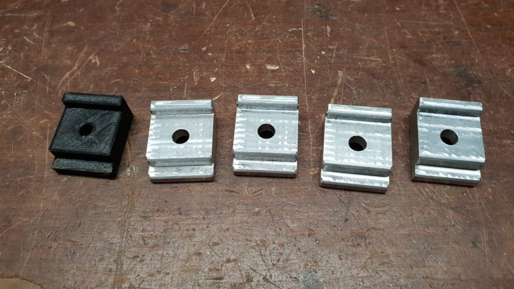
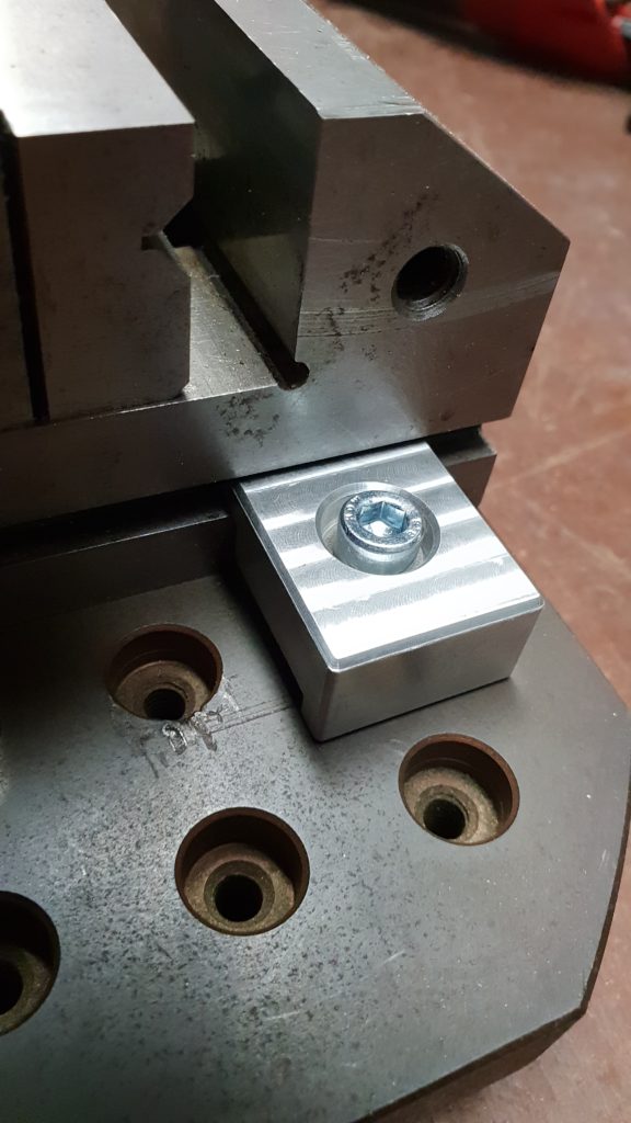
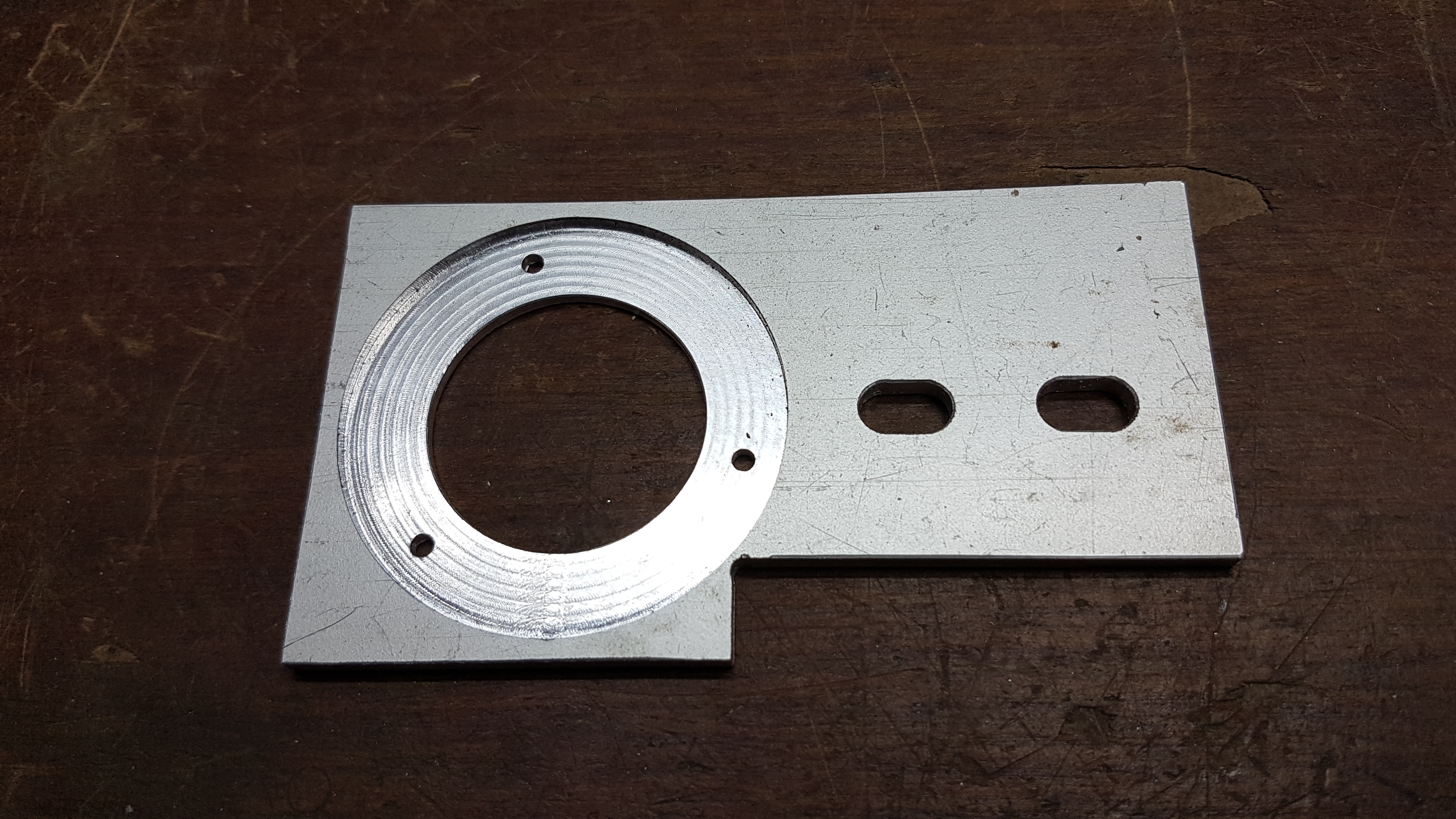
Time to machine some aluminum clamps for a nice vise.
To be used on the palet of my Intelys C3000.
First time I am using 3D printing to check the part before wasting material and time with CNC milling: very useful, let me fix some design flaws before machining!
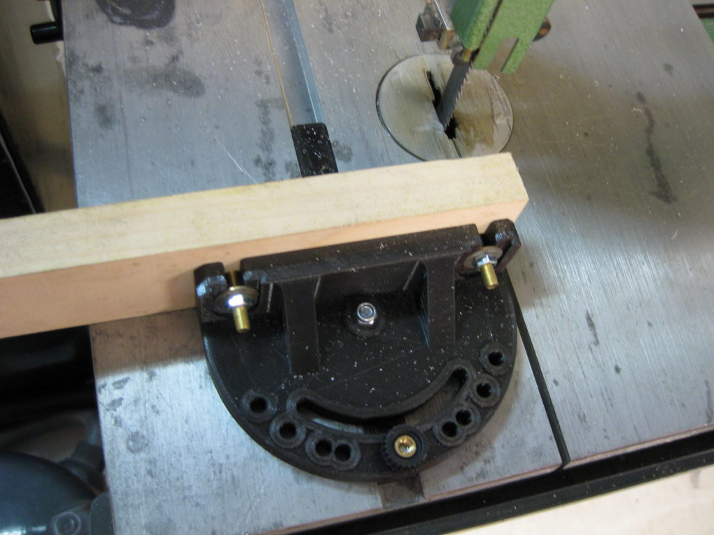
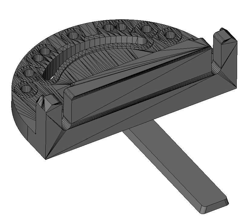
A good friend of mine gave me an Inca 260 bandsaw.
Unfortunately, the original miter gage has been lost.
Found a good design on thingiverse (www.thingiverse.com/thing:505852) that I have tuned for this machine.
This derivative design is available from here: https://www.thingiverse.com/thing:3679405
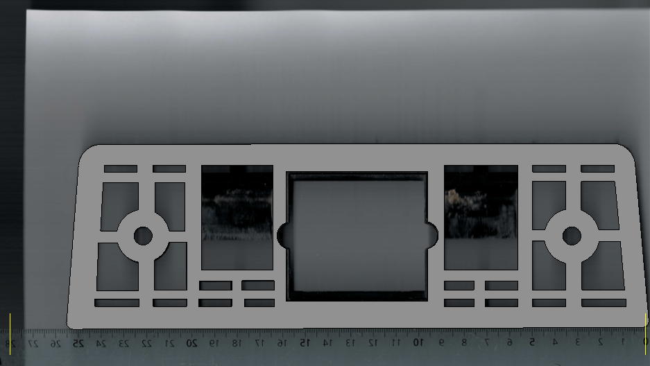
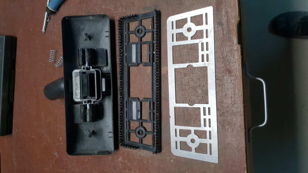
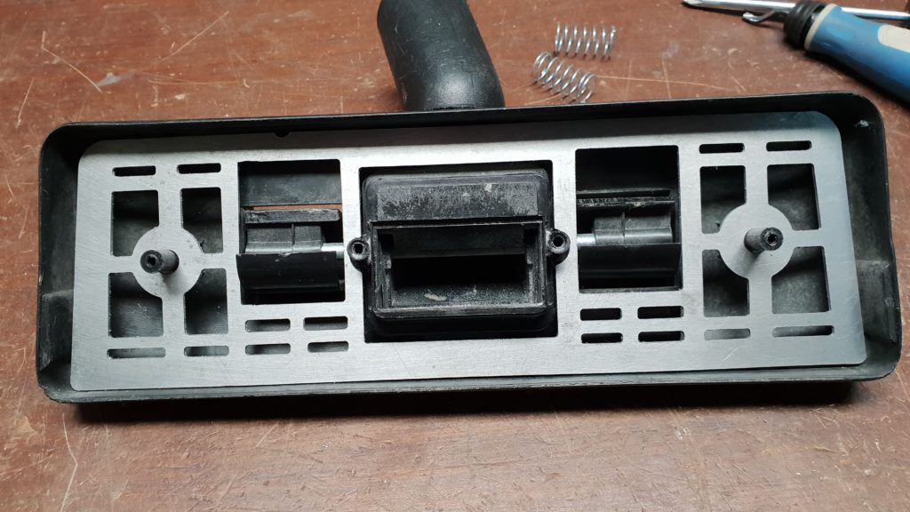
The retractable brush for my vacuum cleaner is broken.
Fixed with an aluminum plate machined on my CNC-6040.
CAD done with ViaCAD, and CAM with BobCAD-CAM.
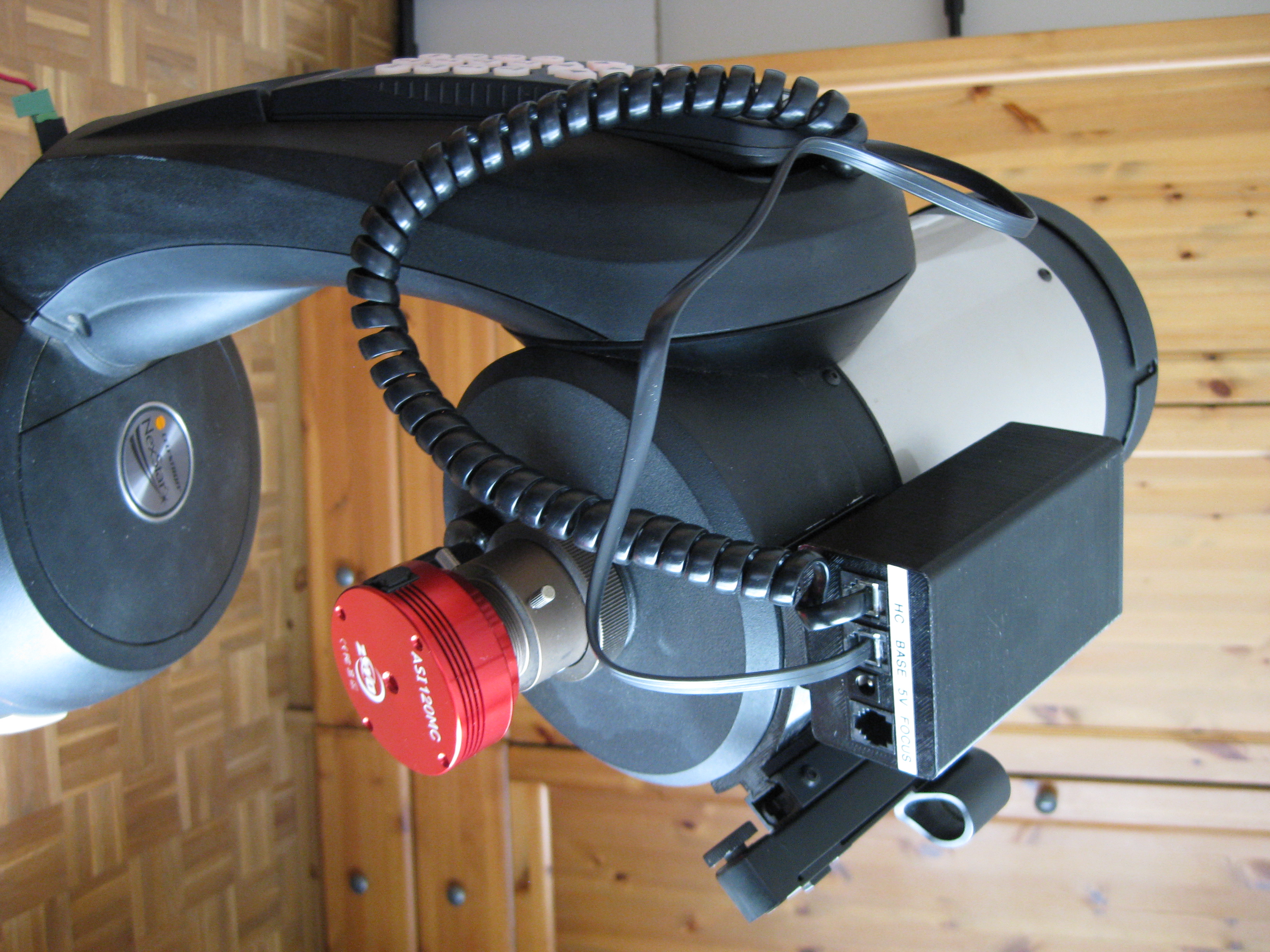
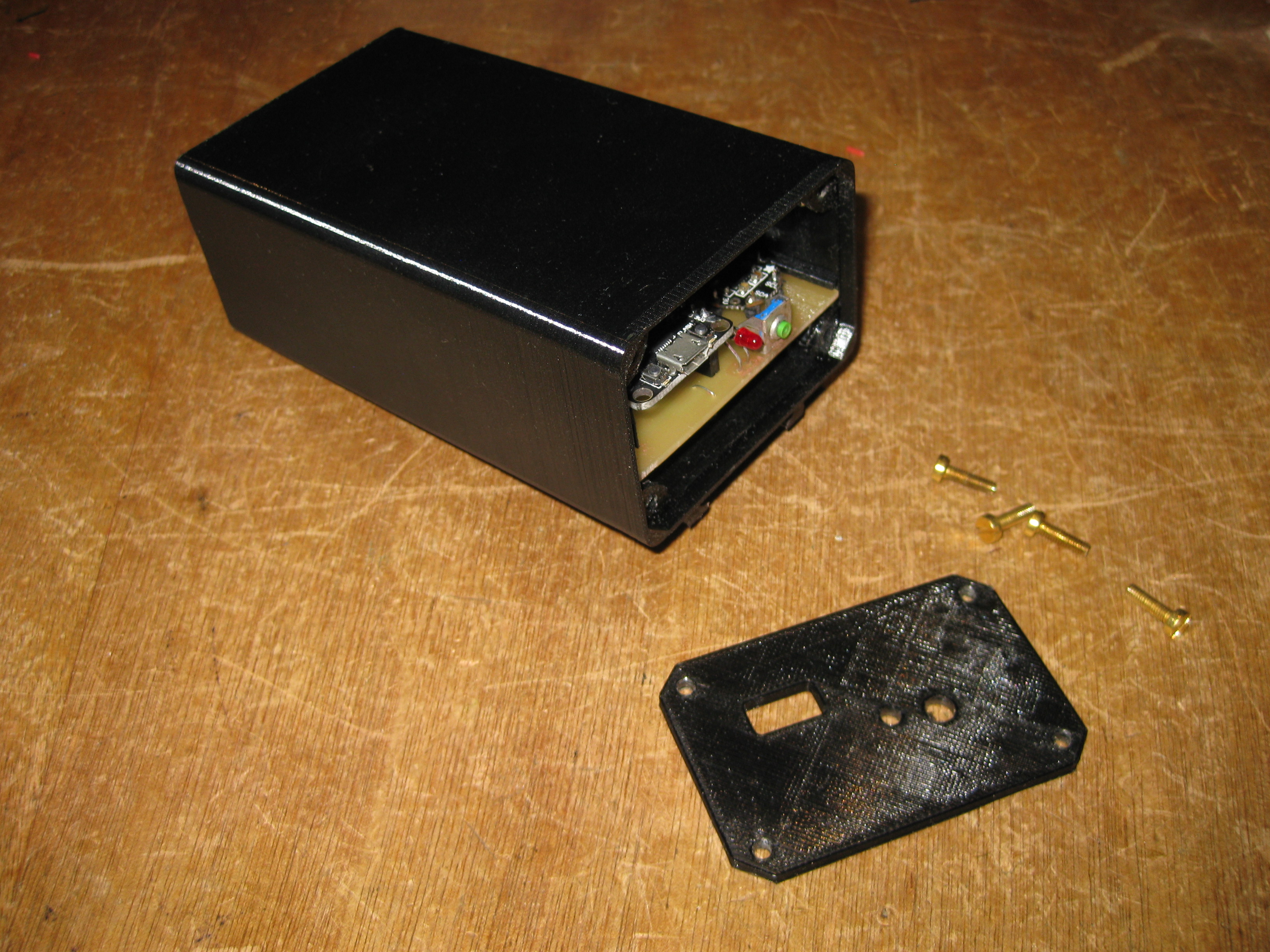
This on-going project is a Wifi interface for an old Y1999 Celestron Nexstar 5 telescope.
The interface box is connected between the handcontroller and the scope mount.
It provides with the following features:
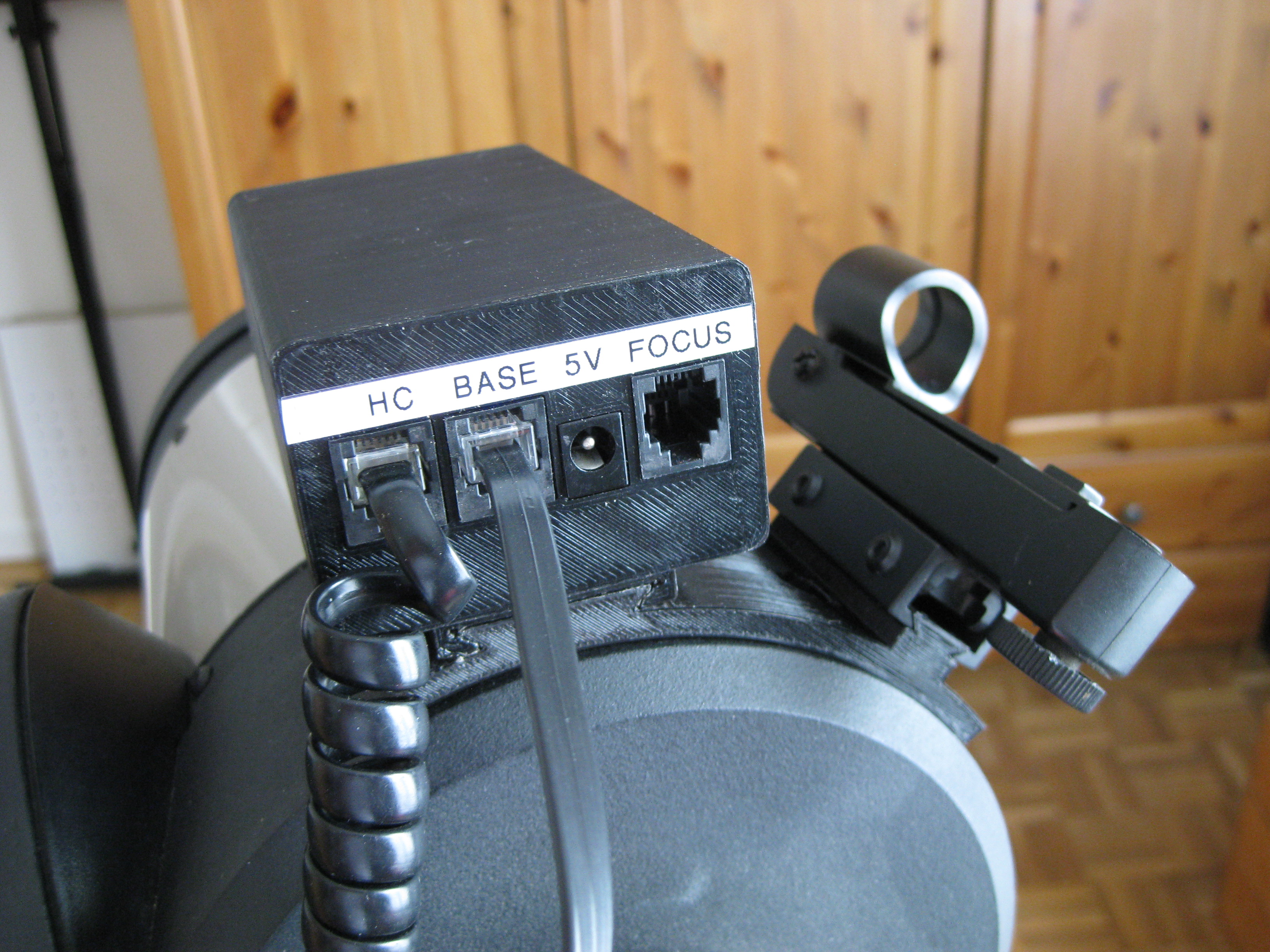
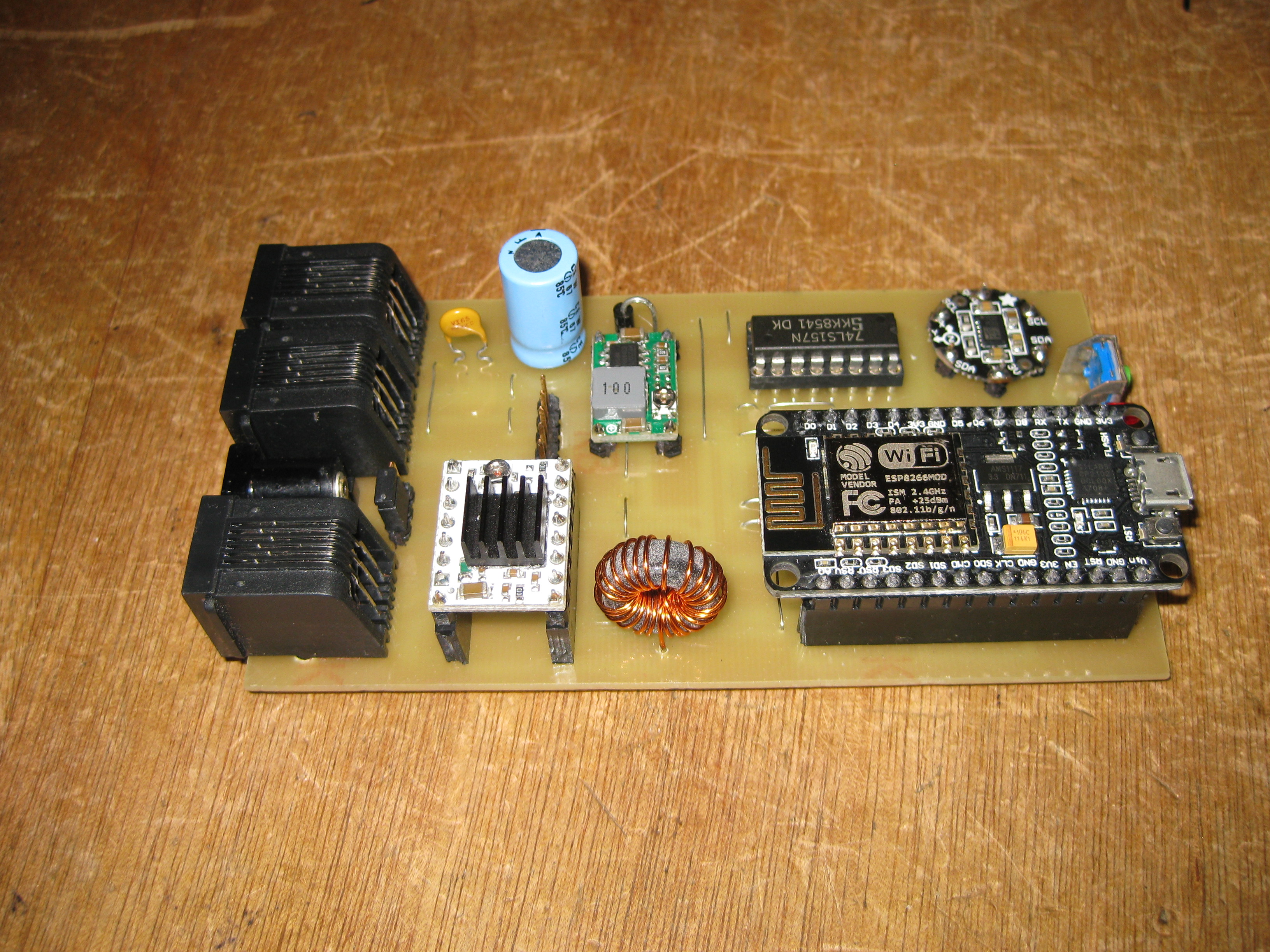
The “brain” is a NodeMCU ESP8266 module with a dedicated software.
I am using ESPUI for the web interface.
The mechanical design is available at https://www.thingiverse.com/thing:2903596

Currently the system is not very stable and is hanging randomly when using the Celestron mount power supply. Looks like the current peaks caused by Wifi transmission are disturbing the serial link. I plan to add an additional GND wire to decrease the impact of current peaks.
The tricky part of the project was understanding the transmission protocol. This is basically a master/slave synchronous proprietary protocol. I have spent hours with a logic analyser before being able to sent my first commands to the telescope controller.
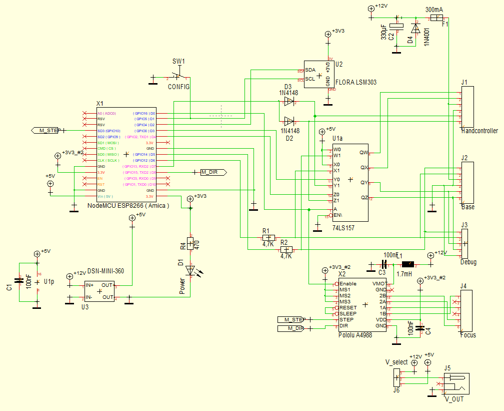
The interface box is connected between the base and the handcontroller so that manual operation remains possible. As the master is the handcontroller, or the wifi box, there is potential conflicts on the serial bus. I have designed an algorithm for detecting manual operation request and switch back the MUX (74LS157) to the handcontroller when required.
The automatic location configuration is based on geo-IP. That is ok for landline connections I have tested. However, there is an issue when using mobile phone for Internet connection because the geo-IP location is not accurate enough. I will add manual location setting in the future.
Here is the breadboard based prototype used to tune the electronics.
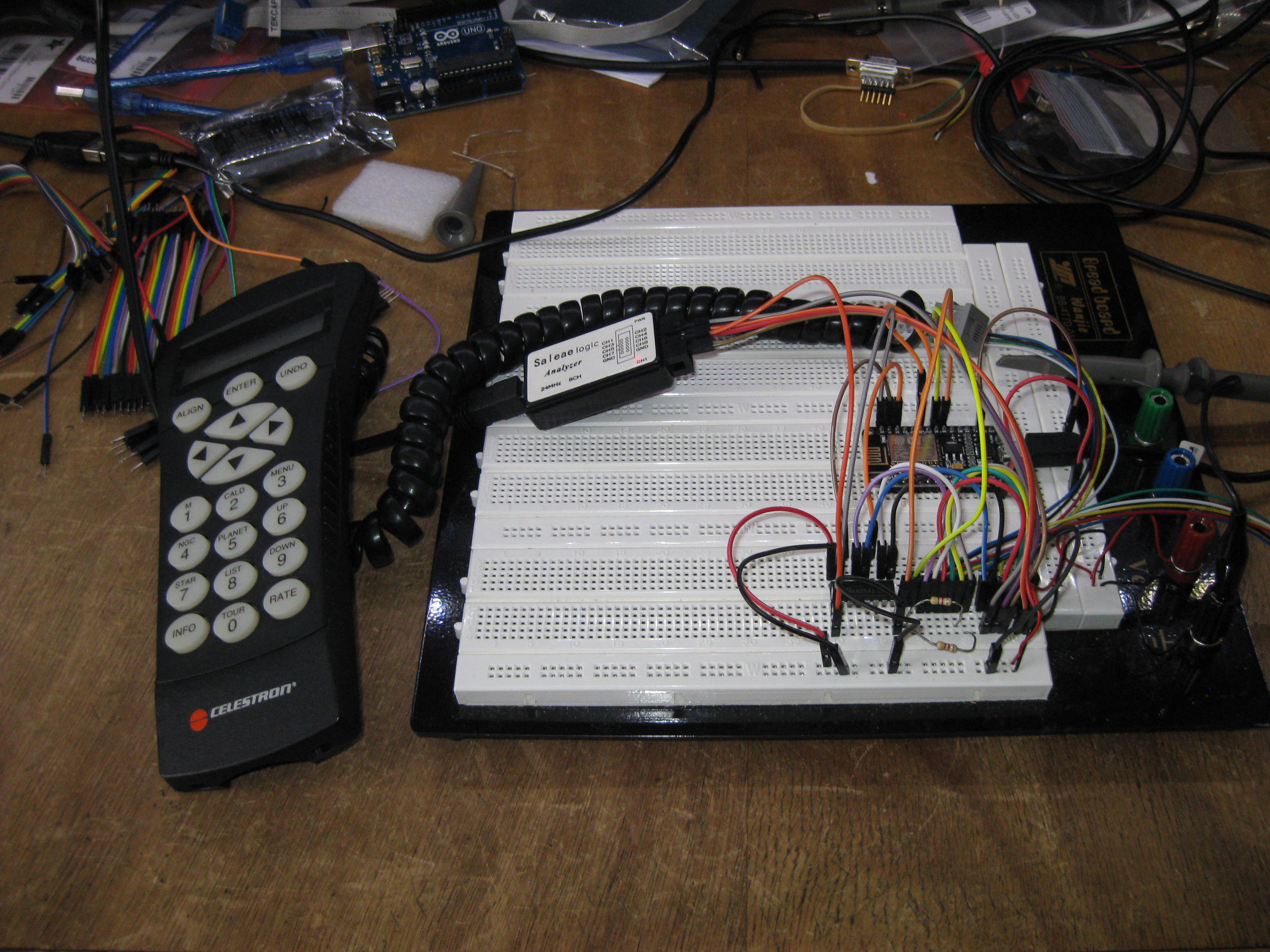
The software is working with this Y1999 handcontroller release. Few years later, the handcontroller electronics and protocol has been modified and is not compatible.

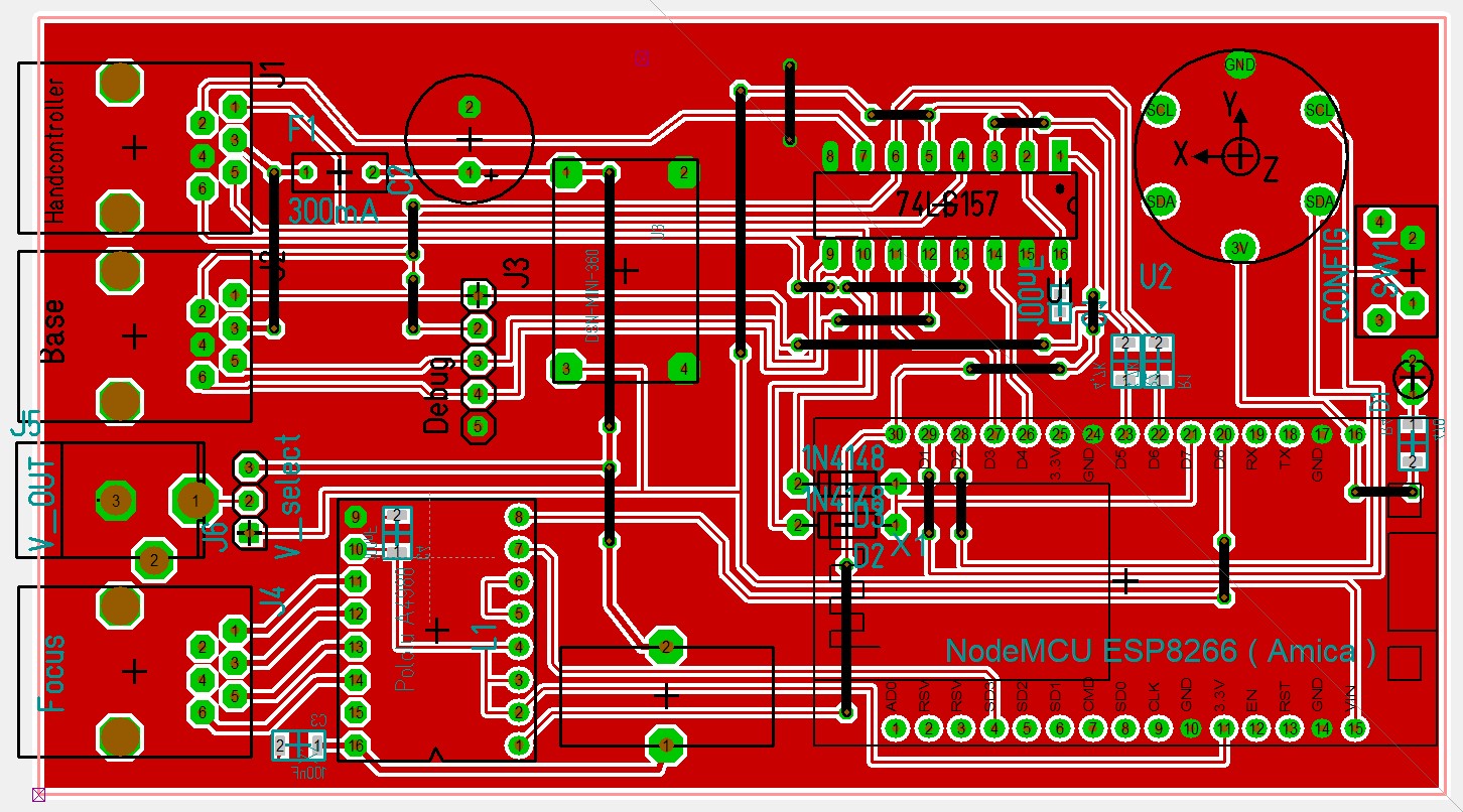
The current schematic diagram (edited on Target!3001 EDA).
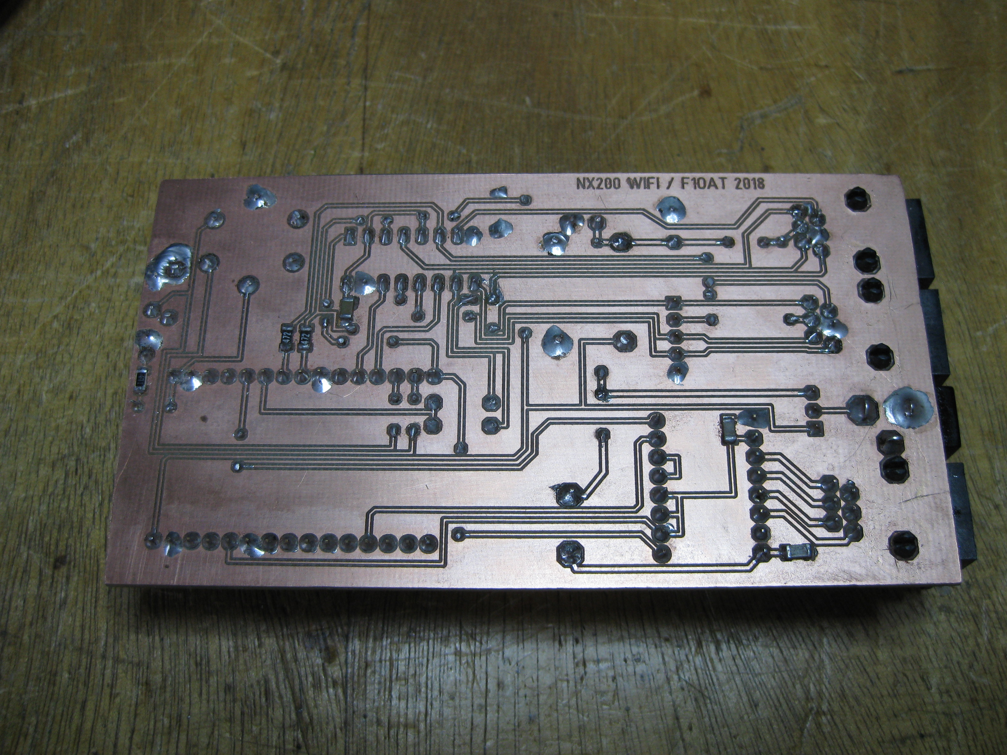
I will publish more stuff when I have achieved good system stability.
Stay tuned!
The goal of this project is to add a PLL lock detection feature to the original GPSDO design by G3RUH (http://www.jrmiller.demon.co.uk/projects/ministd/frqstd.htm).

I have modified the PCB by adding a lock detection circuit based on the monitoring of the PWM signal used to drive the OCXO VTUNE. A spare XOR gate of the 74HCT86 is used to output this signal on the DB9 pin 9 without disturbing the analog loop.
The lock detection job is done by a PICAXE-18X MCU and a 1K/10µF RC filter connected to the analog input (0-5V range). The lock condition is detected by measuring the stability of this signal over 1 minute. Alternatively, one can measure directly the PWM duty cycle with the counting feature of an MCU. That is not the solution I have chosen because the PICAXE pulse width measurement feature does not provide enough resolution.
Additionally, the GPS NMEA output is monitored for satellite and GPS signal quality reporting.
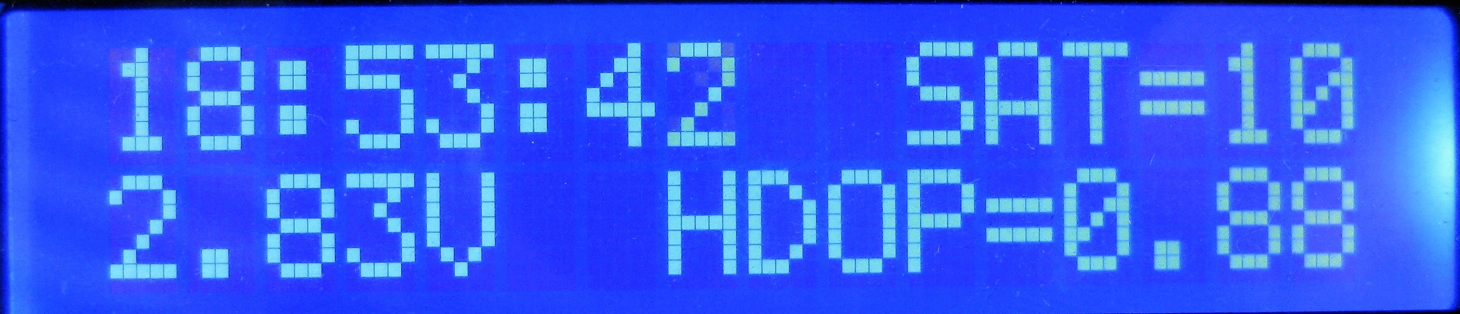
Everything has been integrated in a nice aluminium enclosure with DIY face plate.

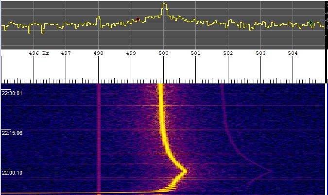
Here is the spectrogram of the 10 MHz output monitored with an ANAN-100D TRX and SpectrumLab. The GPSDO needs about 30 min for stabilization.
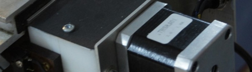
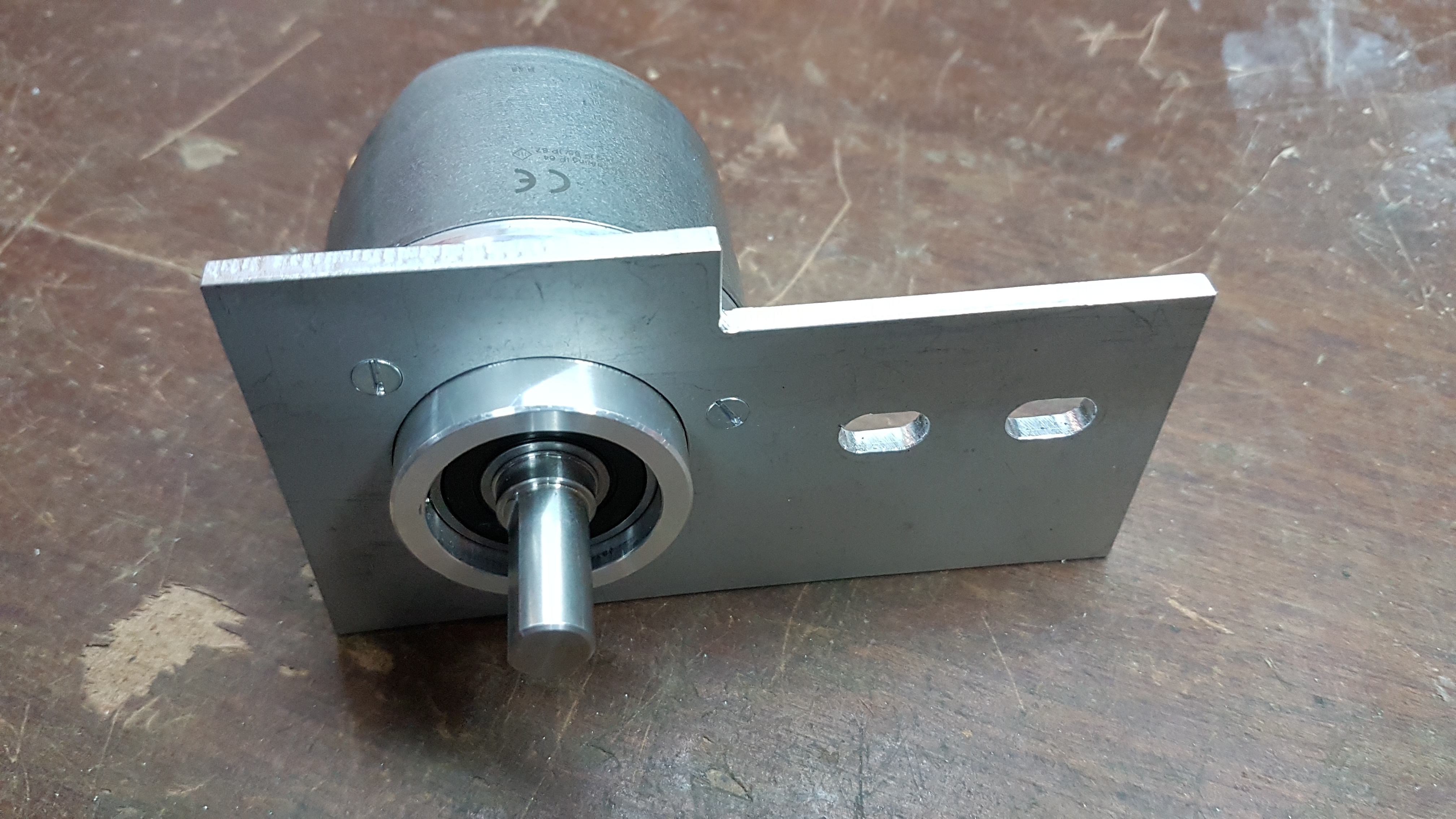
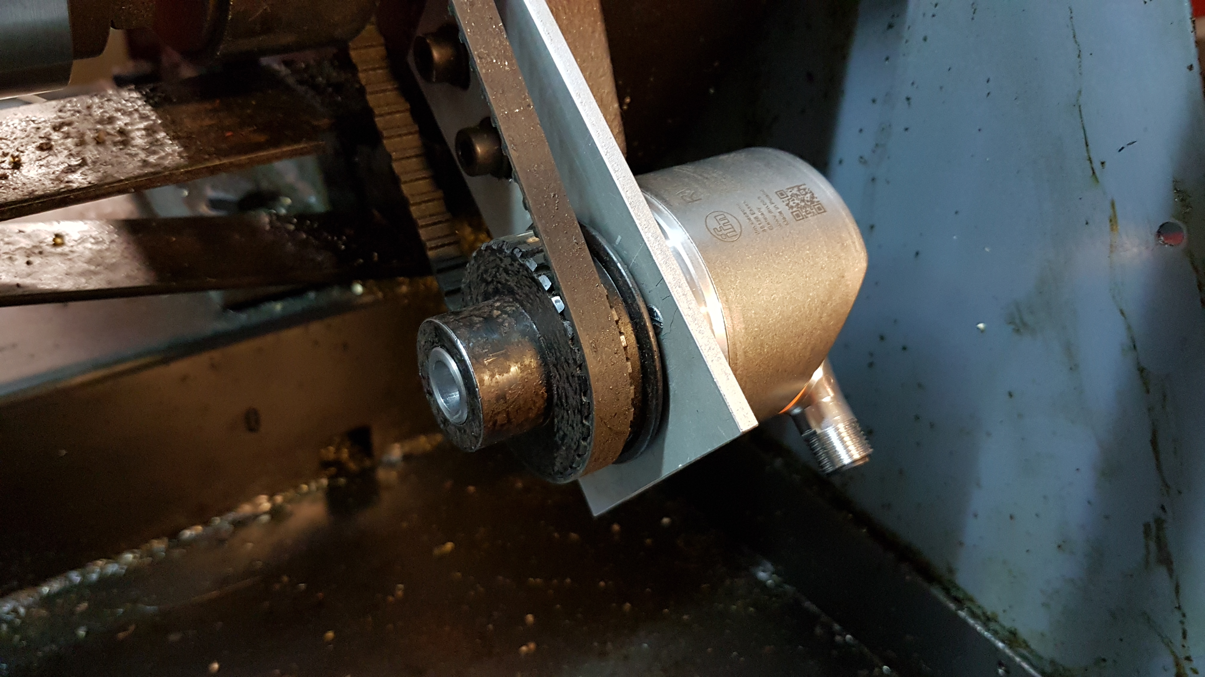
Mounting of a new spindle encoder with high resolution (1024ppr) and quadrature output. The encoder is a RVP510 from ifm.
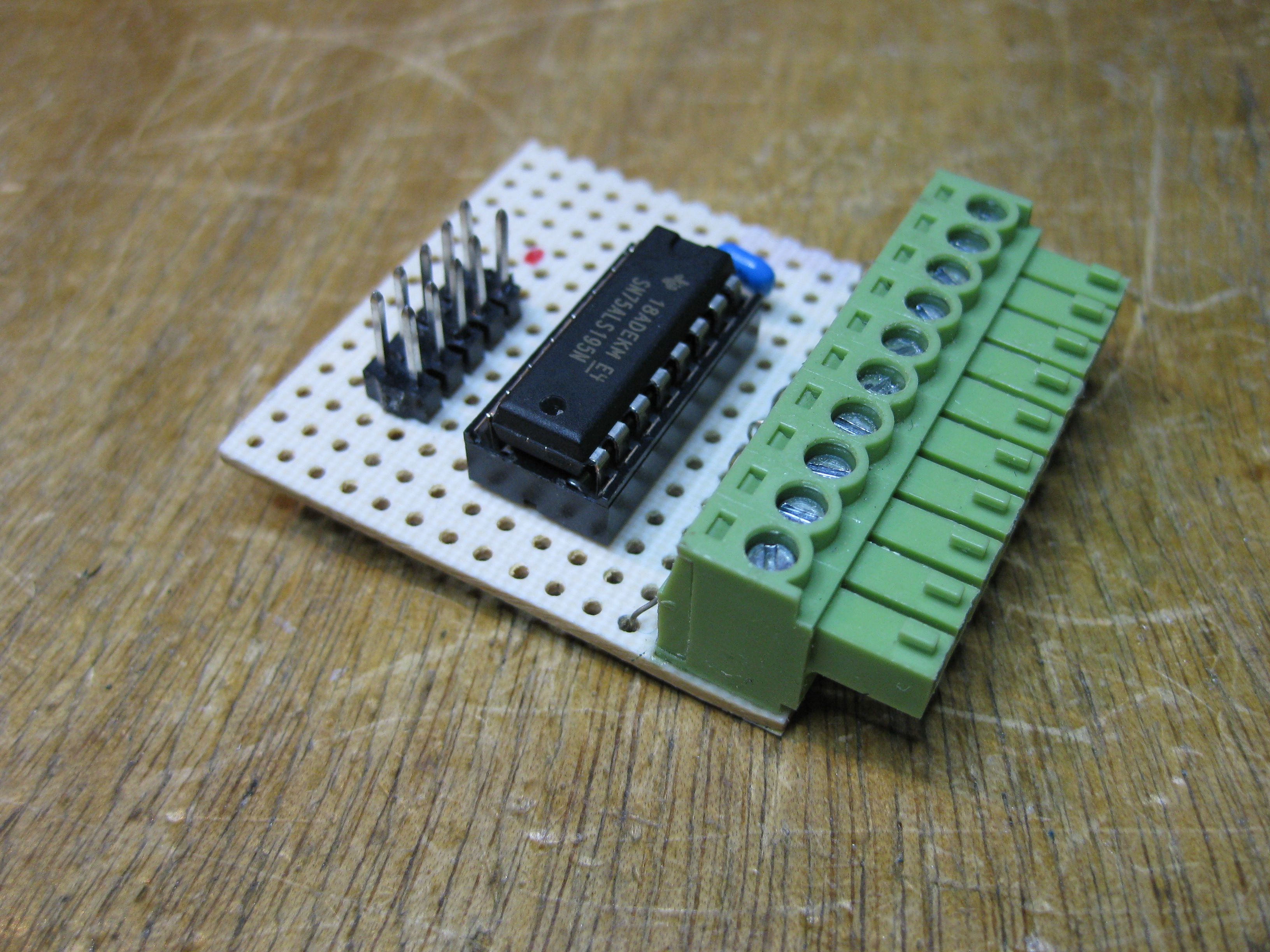
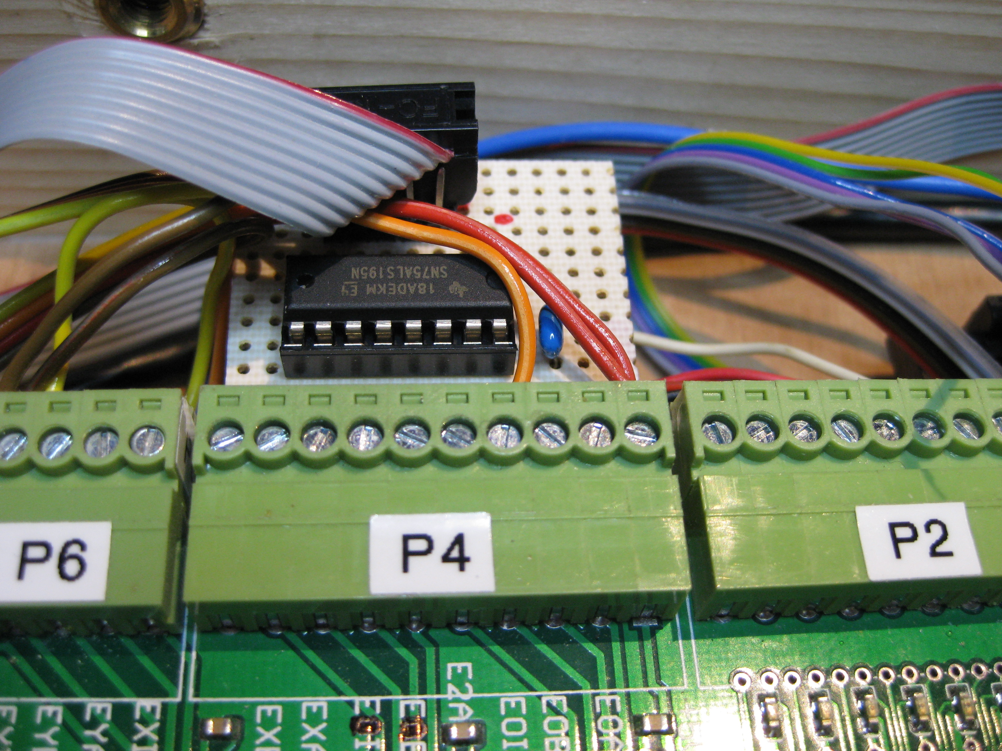
RS-422 to TTL level conversion with a 75ALS195N

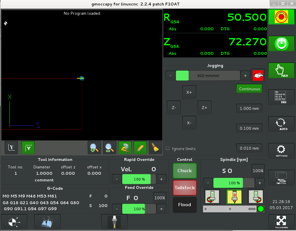
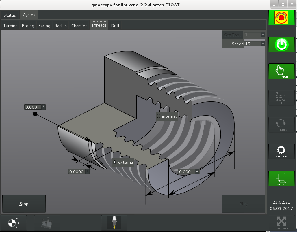
Work in progress: a dark theme for Gmoccapy!