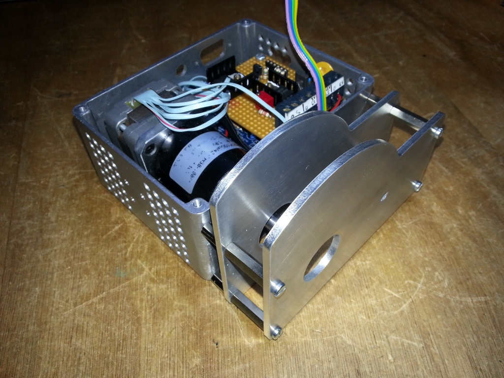
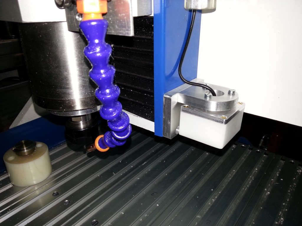
The webcam is mounted along the Z axis. It moves on X and Y, but not Z.
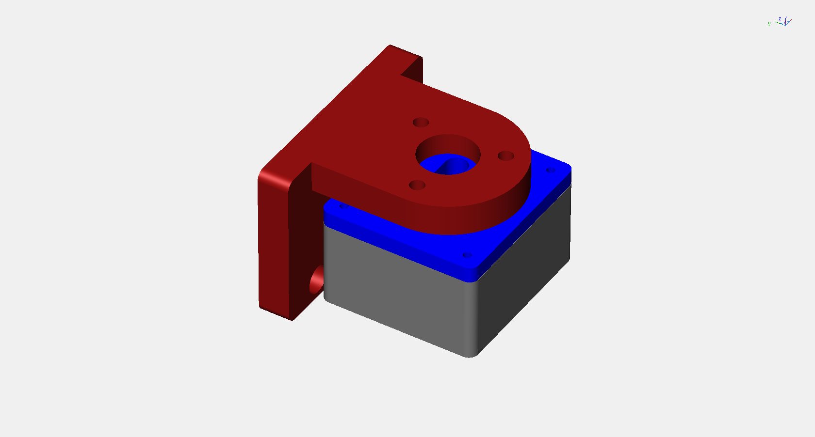
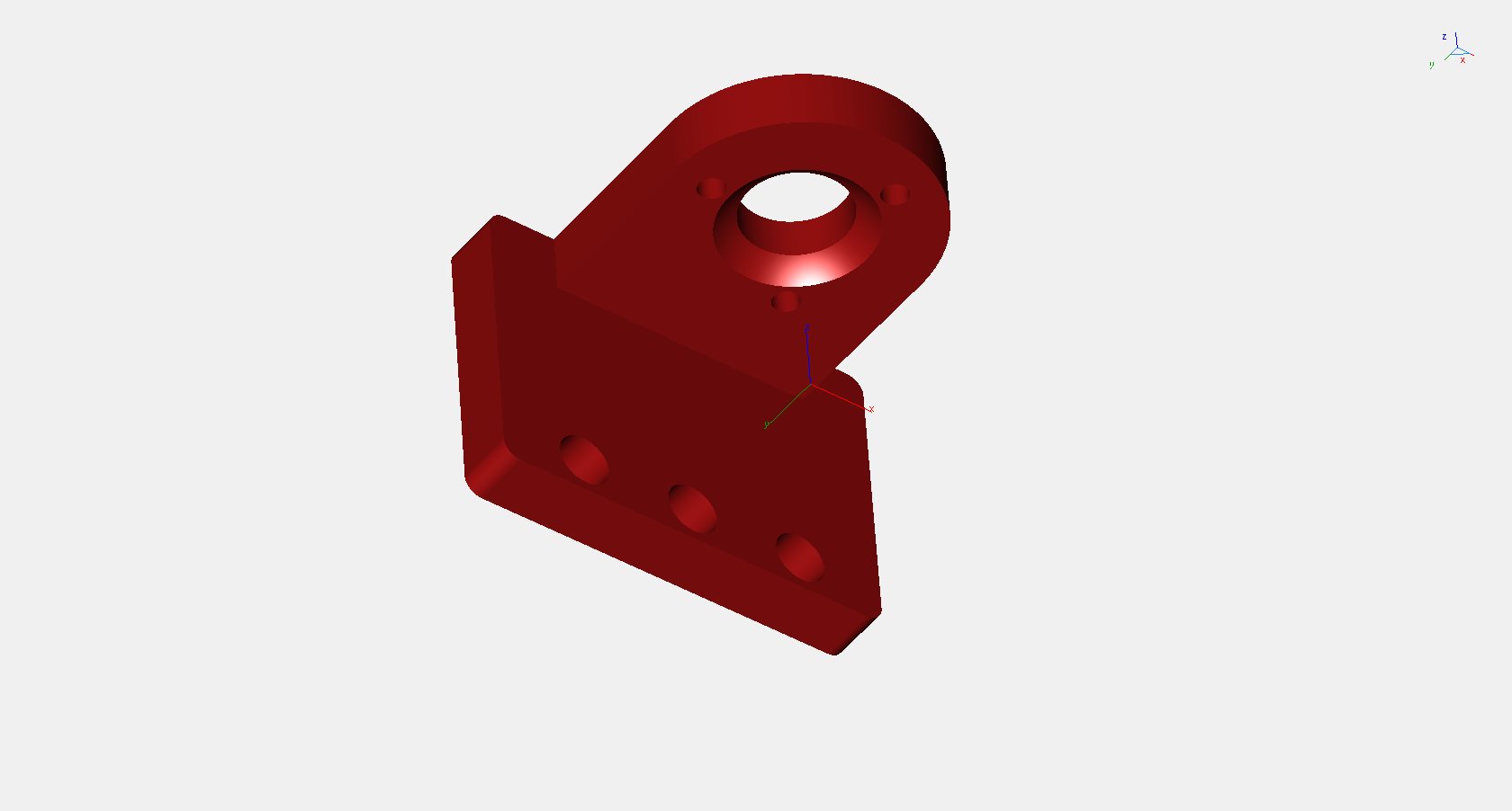
My first idea was to install the webcam on the spindle mount so that it can be moved down to a short distance from the workpiece (too have a large image). However, as the spindle motor height can be adjusted in the mount, it was difficult to find a safe and suitable position for the webcam. So, I went back to the Z axis solution.
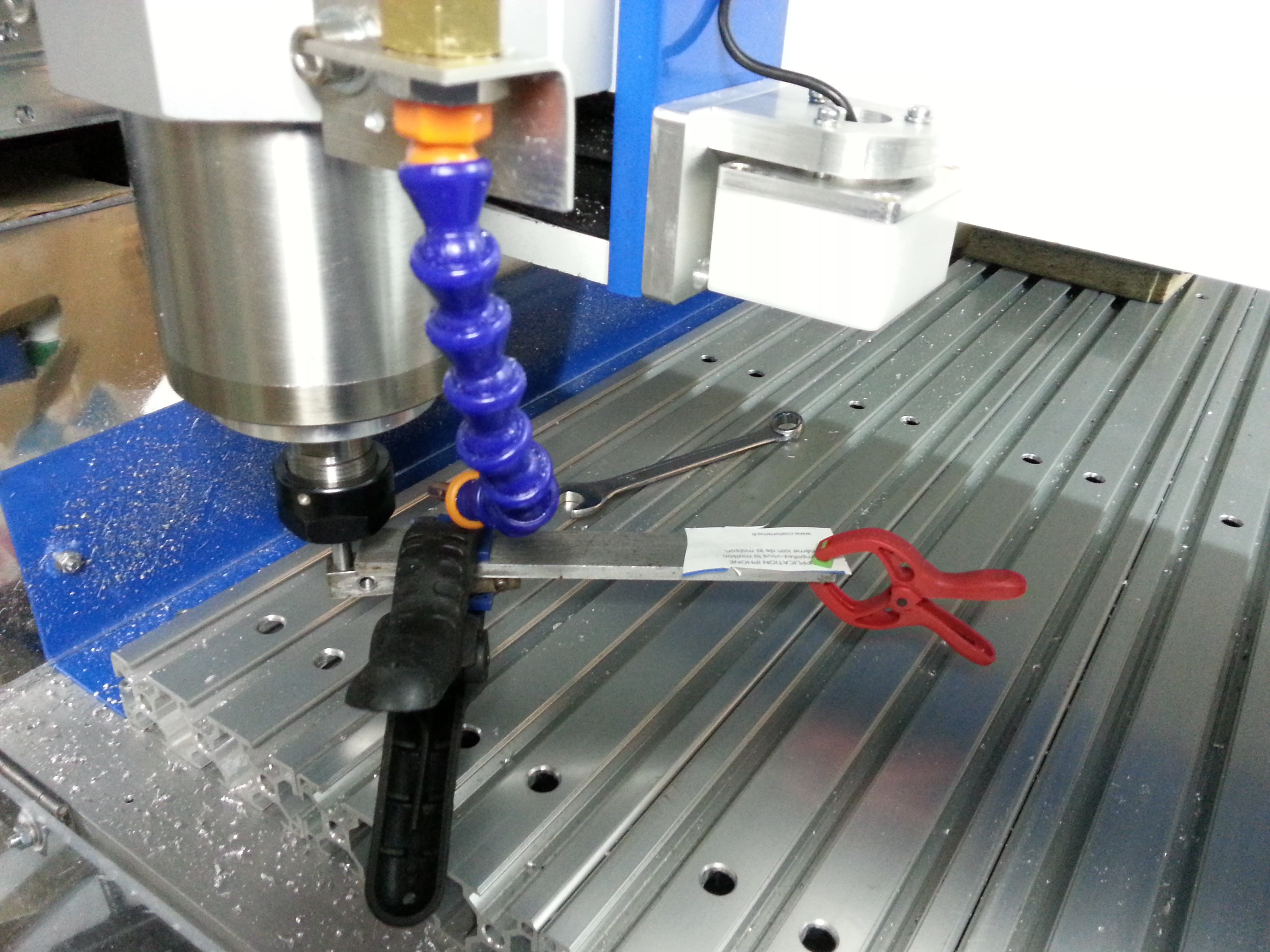
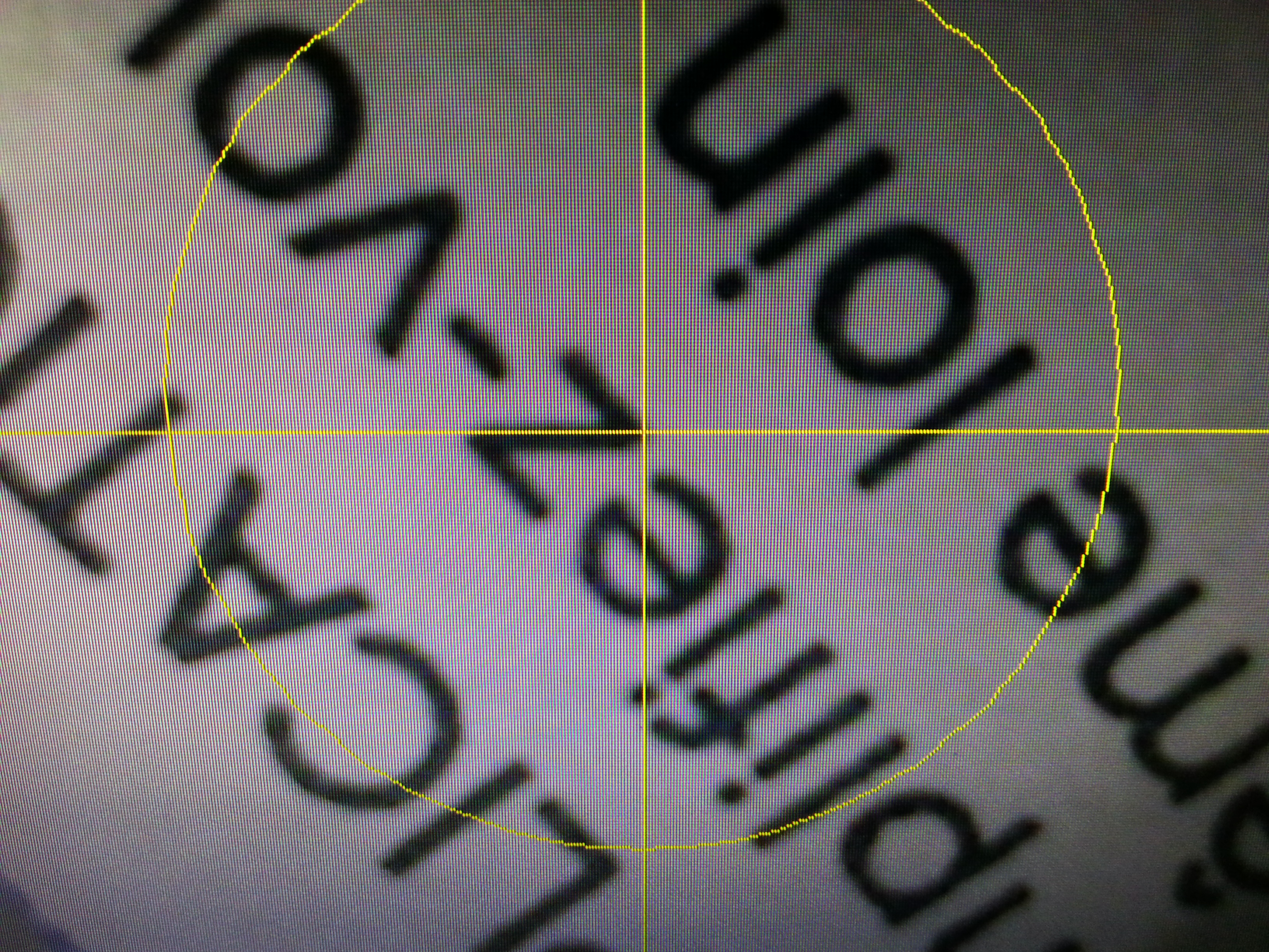
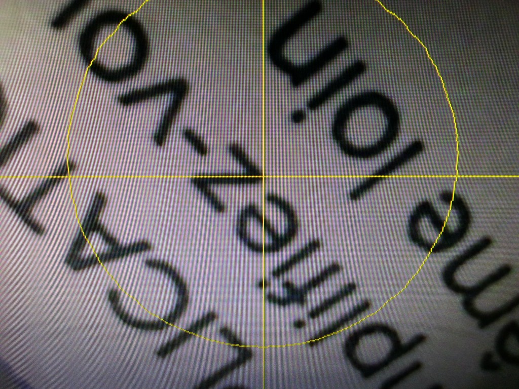
Next step is the vertical alignment of the webcam with Z axis. I used piece of paper (with some writings) attached to a arm mounted in the spindle. Thanks to this configuration, I can move the target up and down. Then I tuned adjustments screws of the webcam so that the crosshair center remain on the same point of the target for any Z position. When this is achieved, the webcam axis is perfectly vertical.

Here, the target at bottom position as seen by the webcam
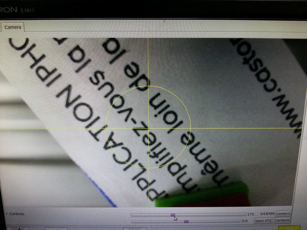
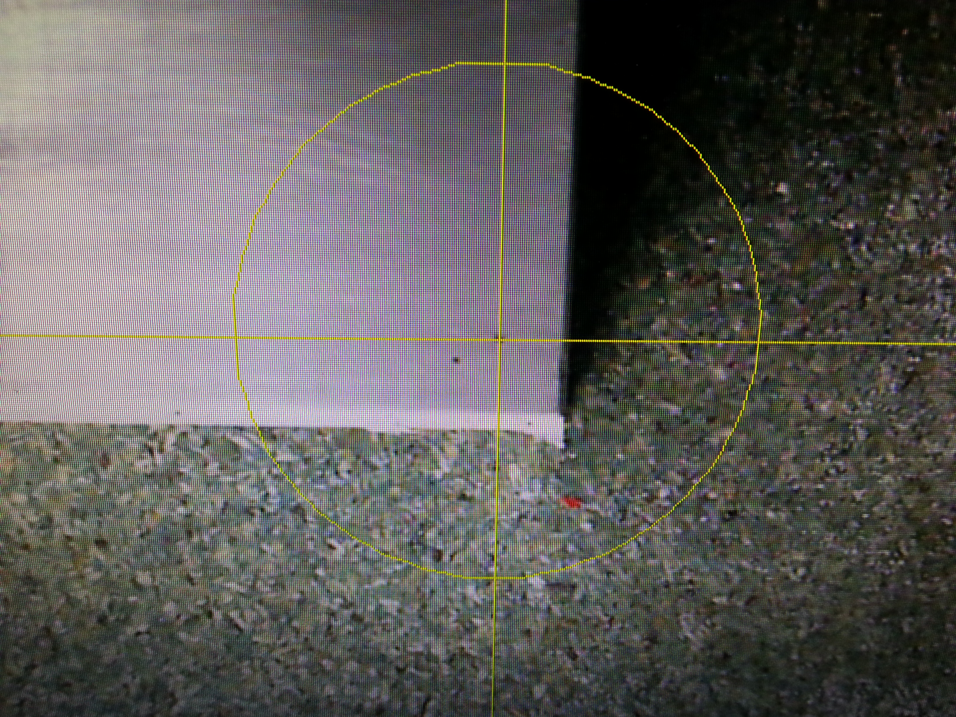
And the same target at top position. No noticeable drift => the alignment is ok.
Next step is the measurement of the offset between the webcam crosshair and the spindle.
I have used a small V-Cutter tool to make a very small hole in a AU4G workpiece. The X/Y position is recorded. The hole as been filled with black color thanks to a soft pencil.
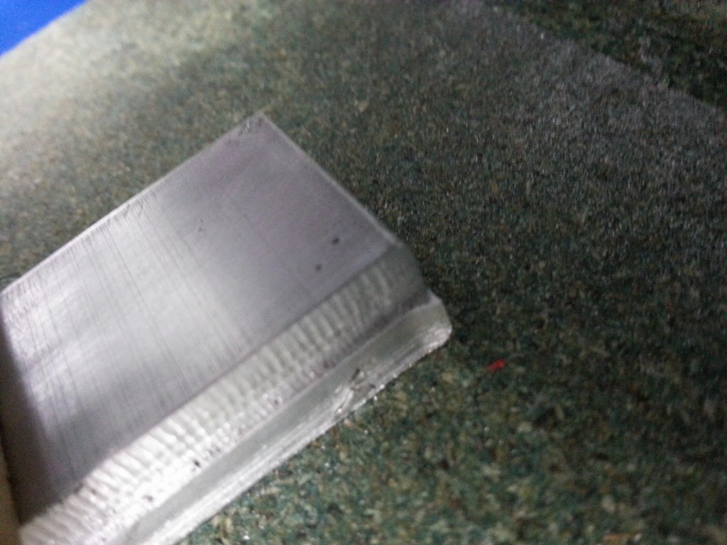
Then I have moved the X/Y axis to get this hole at the center of the crosshair. The delta with the recorded position is the offset to be configured in LinuxCNC.

The optical resolution of the webcam at this distance is about 0.1mm per point. I have tried few pointings and achieved an accuracy better than 0.05mm. Surprisingly, that is better than pixel resolution. I think that is possible because we can see when the hole stands between 2 pixels.