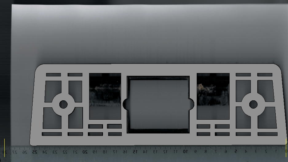
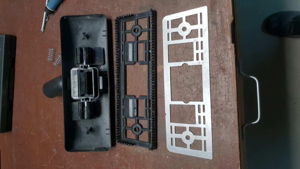
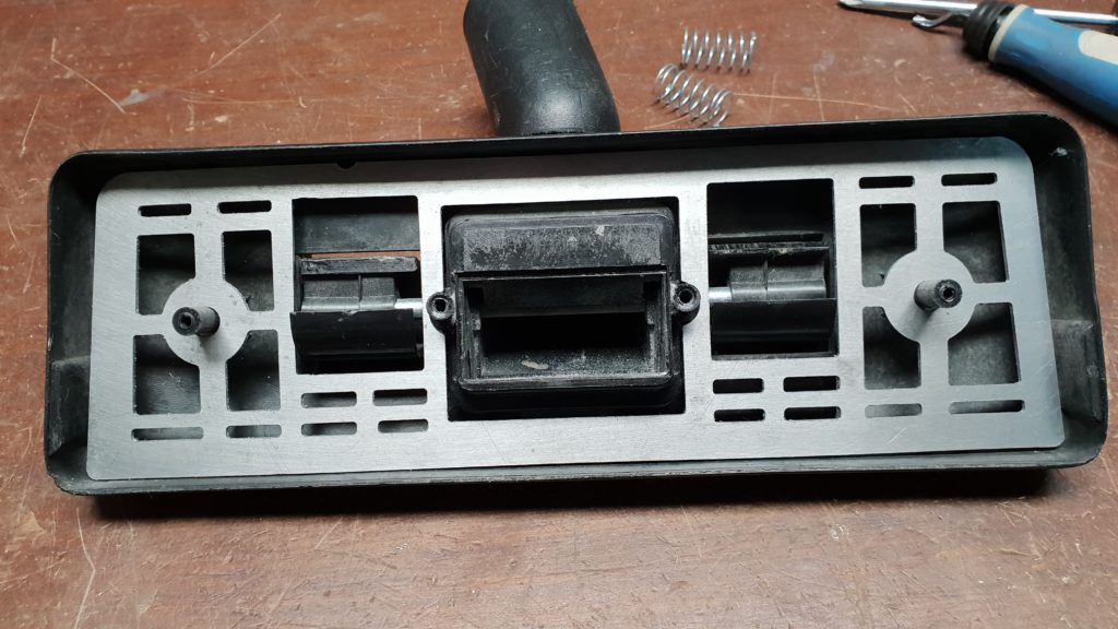
The retractable brush for my vacuum cleaner is broken.
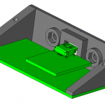
Fixed with an aluminum plate machined on my CNC-6040.
CAD done with ViaCAD, and CAM with BobCAD-CAM.
The retractable brush for my vacuum cleaner is broken.
Fixed with an aluminum plate machined on my CNC-6040.
CAD done with ViaCAD, and CAM with BobCAD-CAM.
3D mesh captured with David Laser Scanner.
G-CODE file generated with trial version of Deskproto.
Milling job achieved on a www.cnc-shop.ch CNC-6040 router and harmonic drive based fourth axis.

BobCAD-CAM is able to manage multiple machine setups in the same project. This is a very useful feature when the workpiece should be cut in several phases with a different fixture for each of them. Below an example with 3 machine setups.
![BobCAD V26 - [Multi Setups]_2015-02-09_22-20-50](https://blog.f1oat.org/wp-content/uploads/2015/02/BobCAD-V26-Multi-Setups_2015-02-09_22-20-50.png)
The generated G-Code file contains all operations in the same file, except if you enable manually only one fixture. So, saving one different G-Code file for each machine setup is possible, but quite painful and risky.
To solve this issue, I have designed a custom BobCAD-CAM postprocessor and a dedicated LinuxCNC/Gmoccapy panel to select from one single G-Code file the operations to be executed for a given machine setup. Also, the Gremlin preview is automatically updated according to the selected machine setup. Here is a video showing how it works:
In the BobCAD-CAM generated G-Code file, the section associated to each machine setup is surrounded by if / elseif / endif statements for dynamic selection.
...
(Machine Setup - 1  Facing)
(FACING)
O100 if  [ #<_selected_setup> EQ 1 ]
T1 M6
G53 G0 Z#<_ini [ AXIS_2 ] SAFE_POSITION>
S15915
M3
G0 X60.150 Y-22.600
M7 (MIST COOLANT)
G0
(Machine Setup - 2  Pocket)
(POCKET)
M5
T2 M6
S3559
M3
M7 (MIST COOLANT)
G0
G0 X5.969 Y.000
G0 Z35.480
...
(NEXT MACHINE SETUP - Machine Setup - 2)
O100 elseif  [ #<_selected_setup> EQ 2 ]
T1 M6
G53 G0 Z#<_ini [ AXIS_2 ] SAFE_POSITION>
....
(NEXT MACHINE SETUP - Machine Setup - 3)
O100 elseif  [ #<_selected_setup> EQ 3 ]
....
G0 Z25.480
G0 Z55.800
O100 endif
M5
M30
The #<_selected_setup> is a custom named parameter linked to a Gmoccapy panel where the setup number can be selected from 1 to 6.
For those who are not using Gmoccapy or LinuxCNC, another option is to get the chosen machine setup by reading an analog input with a M66 statement.
I have spent some hours to configure properly my BobCAD-CAM postprocessor for good result. One tricky aspect is the tools management: if the tool does not change from one machine setup to the next one, the original postprocessor does not include any further tool change statements in the G-Code file. This is not compatible with my O100 if/elseif/endif hack because, the tool change sequence would be issued only for first machine setup. So, I have added a systematic tool change in the following section of the posprocessor:
16. Machine Setup Change
	" "
	"(NEXT MACHINE SETUP - ",setup_name,")"
	" "
	n,"O100 elseif ","[","# EQ ", program_block_5, "]"
	n,t,"M6"
	n,"G53 G0 Z#<_ini","[","AXIS_2","]","SAFE_POSITION>"
	n,s
	n,spindle_on
	n,rapid_move,force_x,xr,force_y,yr,rotary_xyr_angle
	n,program_block_1
	"G0"
	output_rotary_angle
I am not yet fully happy with this solution because I have some unnecessary tool change requests in some situations. But, at least it works, in any case!
I have now to test this modification on the real machine … Stay tuned!
This gallery contains 4 photos.
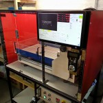
After few days of wood cutting, drilling, painting, 3D printing, etc … here the result: a brand new enclosure for my CNC-6040. No more safety glasses needed when running!
This gallery contains 7 photos.
The original CNC-Shop control box uses a 0-10V board to drive the VFD spindle speed. This is fully supported by LinuxCNC. However, it needs some tuning of the analog levels for proper operation and there is no feedback on the … Continue reading
This gallery contains 4 photos.
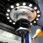
This lighting ring is designed for 18 white LEDs. To be mounted on a 2200W VFD spindle for a milling machine (80 mm overall diameter and 63 mm mounting location). With 12V power supply, group LEDs by 3 units in … Continue reading
The wrapper has been updated to Gmoccapy 1.1.4 currently available in LinuxCNC 2.6 pre release.
JOG-WHILE-PAUSED feature has been disabled because lack of time to adapt to new Gmoccapy.
New package available here: https://blog.f1oat.org/linuxcnc/
Here is a new test showing the resolution we can achieve with the HD5000 when the workpiece is at 25mm distance. Metric units.

A very useful new feature added to my LInuxCNC config: JOG-WHILE-PAUSED based on M60 remap and Gmoccapy modifications.
I have designed a sharedvar class to exchange data between Gmoccapy and the Python code called by REMAP.
The native pause buttons is fully handled.
Everything looks like a standard M0 behavior, except you have access to all functions as for manual mode during pause.
There is an automatic machine state save/restore included in my modified M60.
The webcam is mounted along the Z axis. It moves on X and Y, but not Z.
My first idea was to install the webcam on the spindle mount so that it can be moved down to a short distance from the workpiece (too have a large image). However, as the spindle motor height can be adjusted in the mount, it was difficult to find a safe and suitable position for the webcam. So, I went back to the Z axis solution.

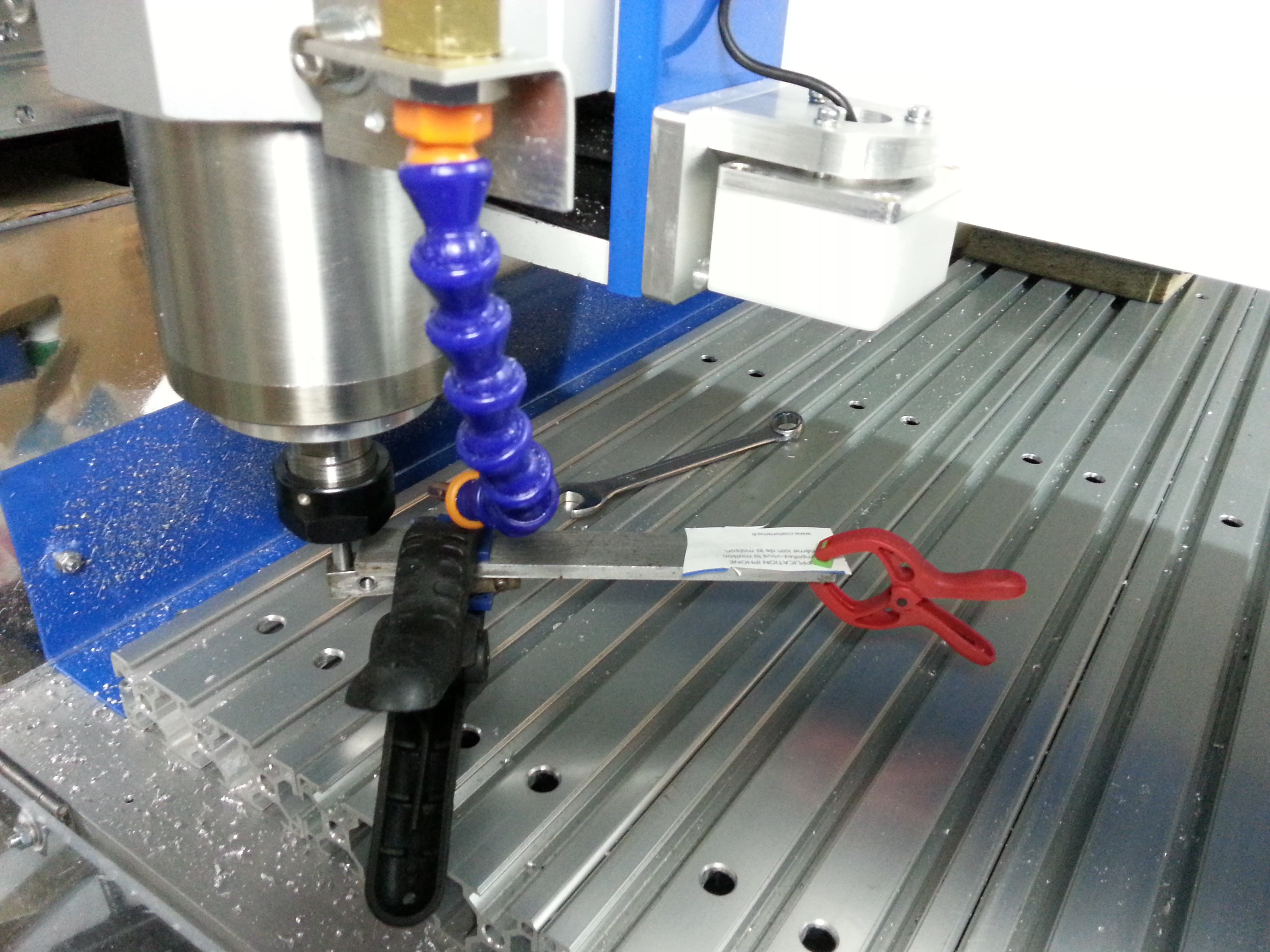
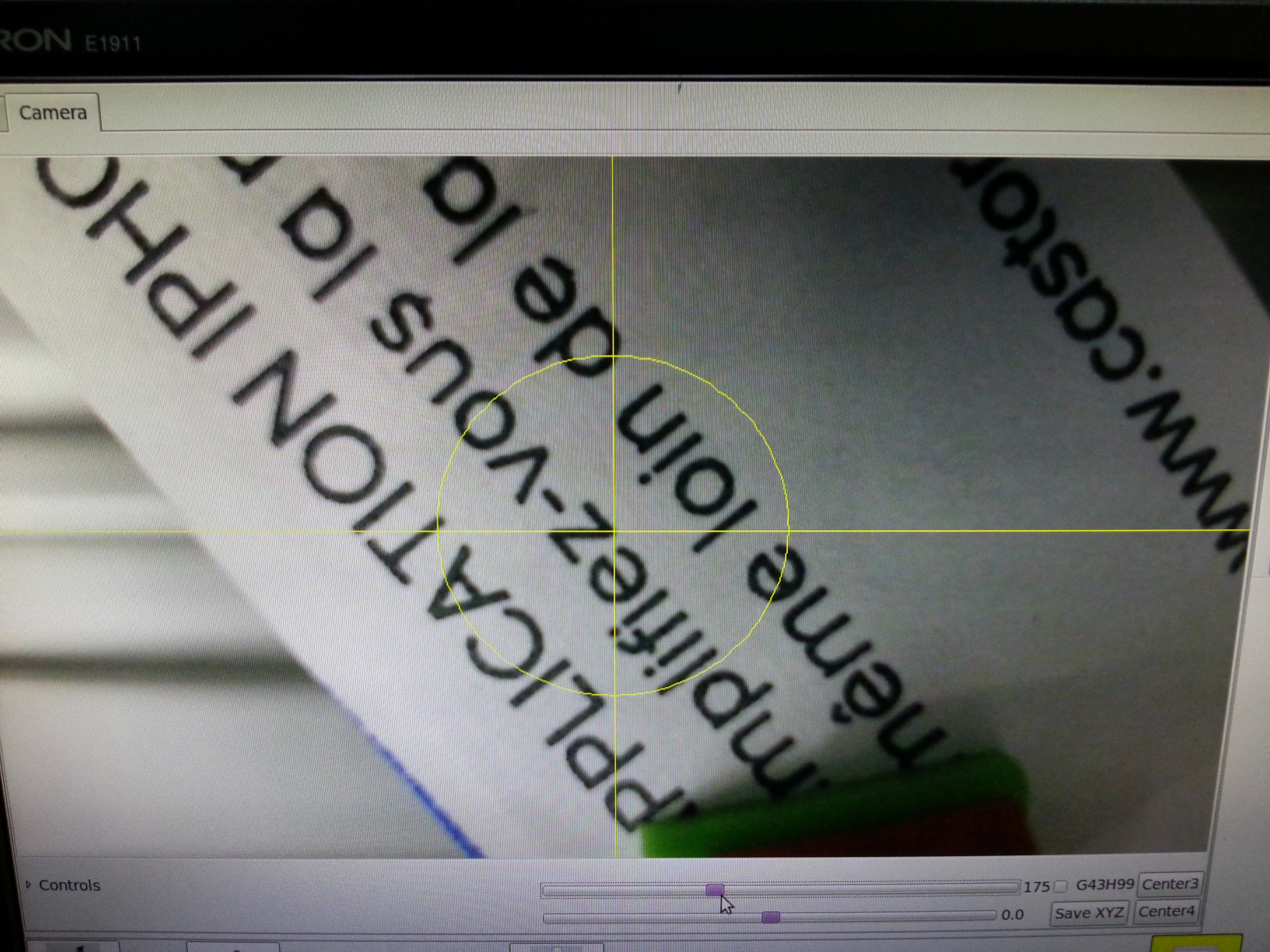
Next step is the vertical alignment of the webcam with Z axis. I used piece of paper (with some writings) attached to a arm mounted in the spindle. Thanks to this configuration, I can move the target up and down. Then I tuned adjustments screws of the webcam so that the crosshair center remain on the same point of the target for any Z position. When this is achieved, the webcam axis is perfectly vertical.
Here, the target at bottom position as seen by the webcam
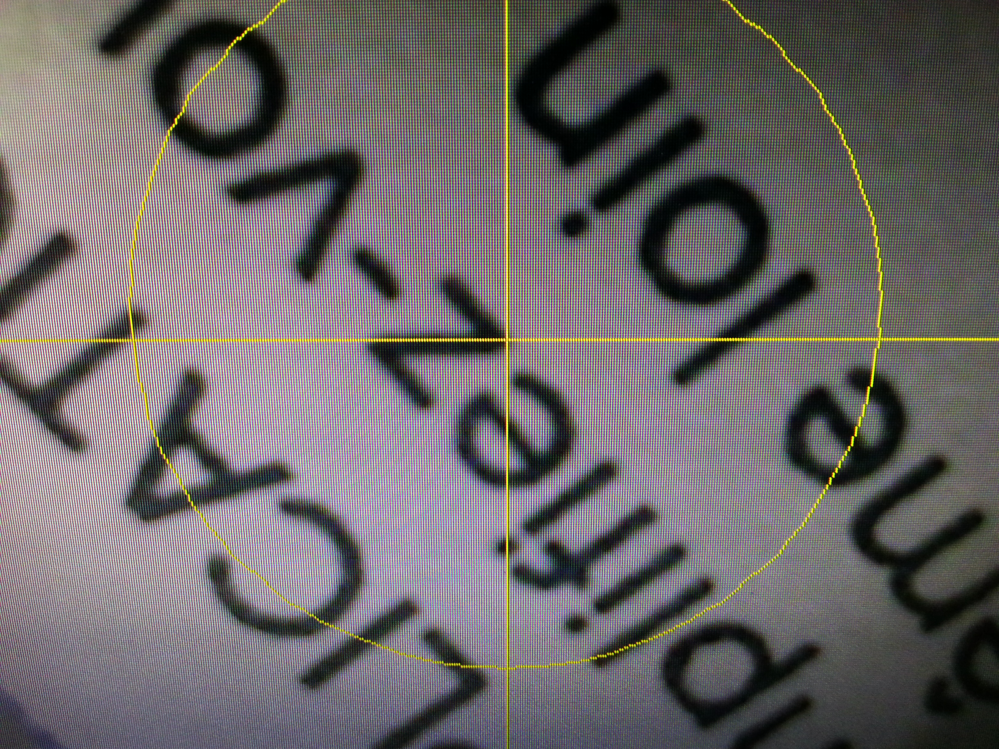
And the same target at top position. No noticeable drift => the alignment is ok.
Next step is the measurement of the offset between the webcam crosshair and the spindle.
I have used a small V-Cutter tool to make a very small hole in a AU4G workpiece. The X/Y position is recorded. The hole as been filled with black color thanks to a soft pencil.

Then I have moved the X/Y axis to get this hole at the center of the crosshair. The delta with the recorded position is the offset to be configured in LinuxCNC.
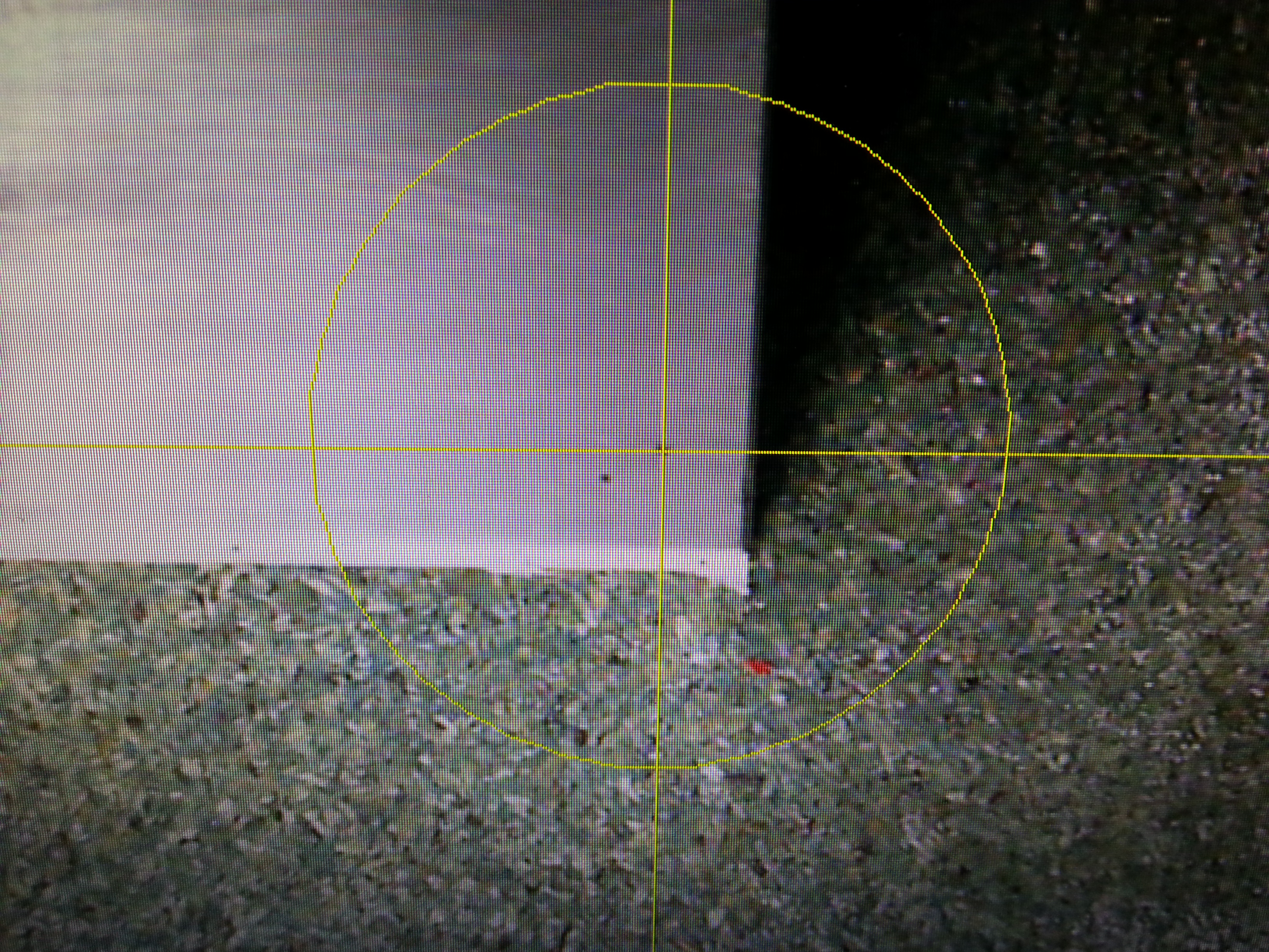
The optical resolution of the webcam at this distance is about 0.1mm per point. I have tried few pointings and achieved an accuracy better than 0.05mm. Surprisingly, that is better than pixel resolution. I think that is possible because we can see when the hole stands between 2 pixels.