A Webcam mounting bracket for machine optical precision pointing

The original idea comes from this post by “catlord”

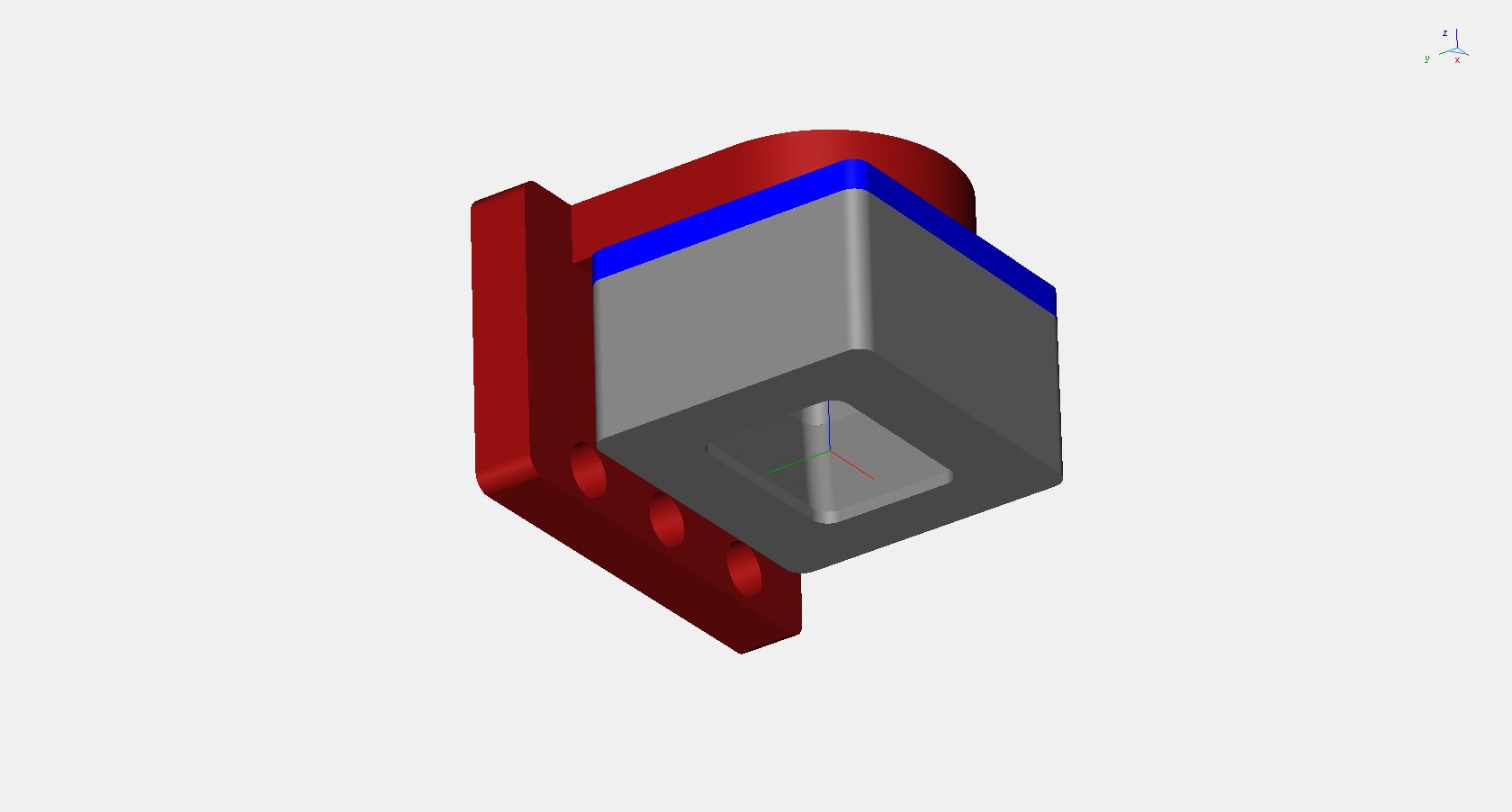
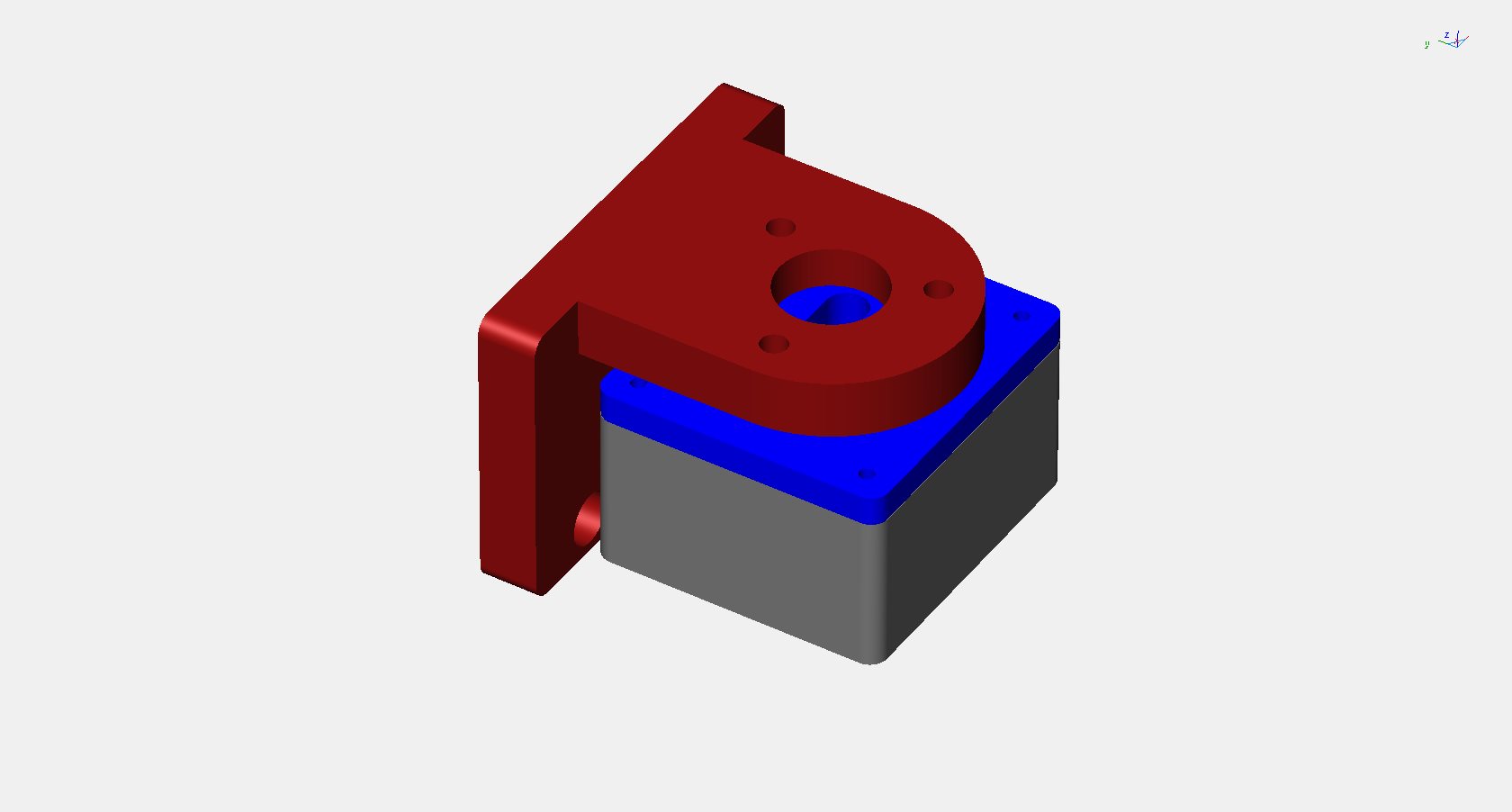
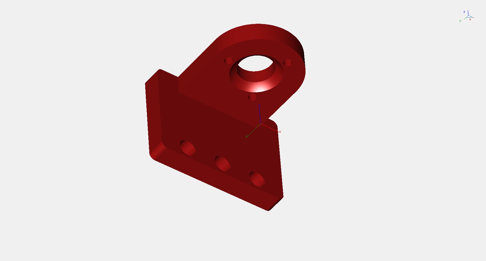
For my project, I wanted a solution for fine alignment of the webcam axis to the Z axis so that pointing is accurate at any distance. I got inspired by the mounting used for telescope secondary mirror, as shown is this video

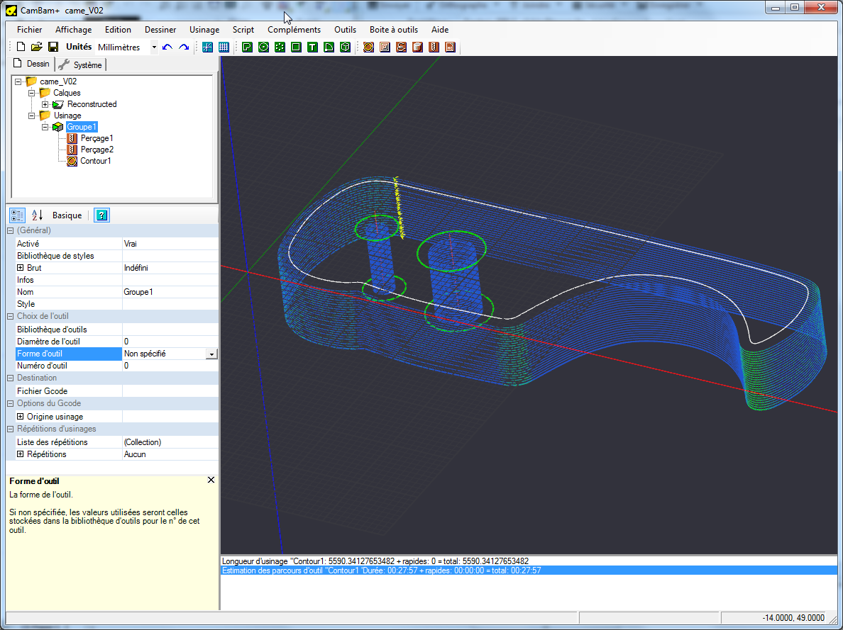
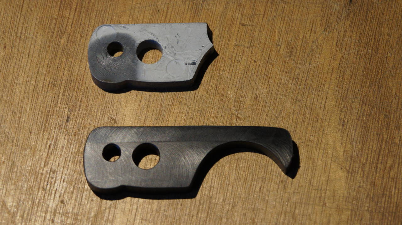
For accuracy and stability concern, my design is based on a ball joint. The fine adjustment is done with 3 screws.

Support HD5000 V12 view01

Support HD5000 V12 view02

Support HD5000 V12 view03

Support HD5000 V12 view04


Good usage of G64 command

I have experienced poor cutting speed with complex curves. The feedrate was not constant, even with G64 command.

After googleing few hours, I found a clue: LinuxCNC needs a tolerance parameter to be able to blend complex curves with true constant feedrate. Now I use “G64 P0.01” which gives 0.01 mm allowed error for the tool path. With this feature I have decrease the machine time from 3 hours down to 40 min for the same job, 1/4 ratio !

Below a video showing my machine cutting POMC at 700 mm/min feedrate.

The CNC mini-milling machine in the box

Here is a new box for noise limitation and safety !
Build with 10 mm and 18 mm medium.
The machine stands on a plate of rubber like material designed for washing machine vibration isolation.
The blue tube is the connection to the external air compressor.

The mill in cooled and lubricated with a home-made microlub.

The oil/air mixer is based on a standard lubricating system. There is a by-pass if only airĀ  flow is required. Currently running with 3.5 bars and a oil flow of 10 drops/min.

The nozzle is based on a Locline modified according to http://www.usinages.com/supports-lubrification-eclairage-entretien/realisation-artisanale-systemes-microlubrification-t9118-60.html

The nozzle hole is 1 mm diameter. With 3.5 bars, the air flow is around 30 liters/min.


First real workpiece

After lot of tuning of my CNC mini-mill, a first real project: the remake of a broken part from a radio mast.

Step #1: an image of the broken part is done with a scanner. Then, the object is reconstructed within TurboCad V12 with a red spline.

Broken part graphical reconstruction

Step #2: the toolpath is computed with Cambam CAM software

Cambam toolpath

Step #3: machining on my homebrew CNC mini-mill

Homebrew CNC mini-mill

Step 4: the remade part with POM-C material

Remake of the broken object

Zoom on the remade object